Coil Unit for Motor Stator

a motor stator and coil unit technology, applied in the direction of dynamo-electric machines, ac commutators, supports/enclosements/casings, etc., can solve the problems of ineffective reduction of the total volume and the limitation of the reduction of the difficulty of miniaturizing the motor. to achieve the effect of reducing the axial height of the motor stator

Active Publication Date: 2011-03-10
SUNONWEALTH ELECTRIC MACHINE IND
View PDF15 Cites 30 Cited by
  • Summary
  • Abstract
  • Description
  • Claims
  • Application Information

AI Technical Summary

Benefits of technology

[0007]An objective of the present invention is to provide a coil unit for a motor stator to reduce the axial height of the motor stator.
[0008]Another objective of the present invention is to provide a coil unit for a motor stator to reduce the volume of the motor stator.
[0010]A coil unit for a motor stator according to the preferred teachings of the present invention includes a plurality of layout layers. At least one coil and a conductive portion electrically connected to the at least one coil are formed on a surface of each of the layout layers. The conductive portions of two adjacent layout layers are electrically connected to each other. An insulting layer is provided between two adjacent layout layers. The coil unit can be coupled to a face of a substrate to form a motor stator with reduced axial height and reduced volume.

Problems solved by technology

However, the stacked silicon steel plates 81 cause limitation to reduction in the axial height of the motor stator 8.
Thus, when the motor stator 8 is utilized in a motor shown in FIG. 2, the total volume and the axial height of the motor can not be effectively reduced, leading to difficulties in miniaturization of the motor.
However, the coils 921 of the coil unit 92 protruding beyond the side of the substrate 91 still has a certain height in the axial direction, leading to difficulties in reduction of the overall axial height of the motor stator 9 and in designs of compact and miniature motors.

Method used


Image

  • Coil Unit for Motor Stator
  • Coil Unit for Motor Stator
  • Coil Unit for Motor Stator

Examples


Embodiment Construction

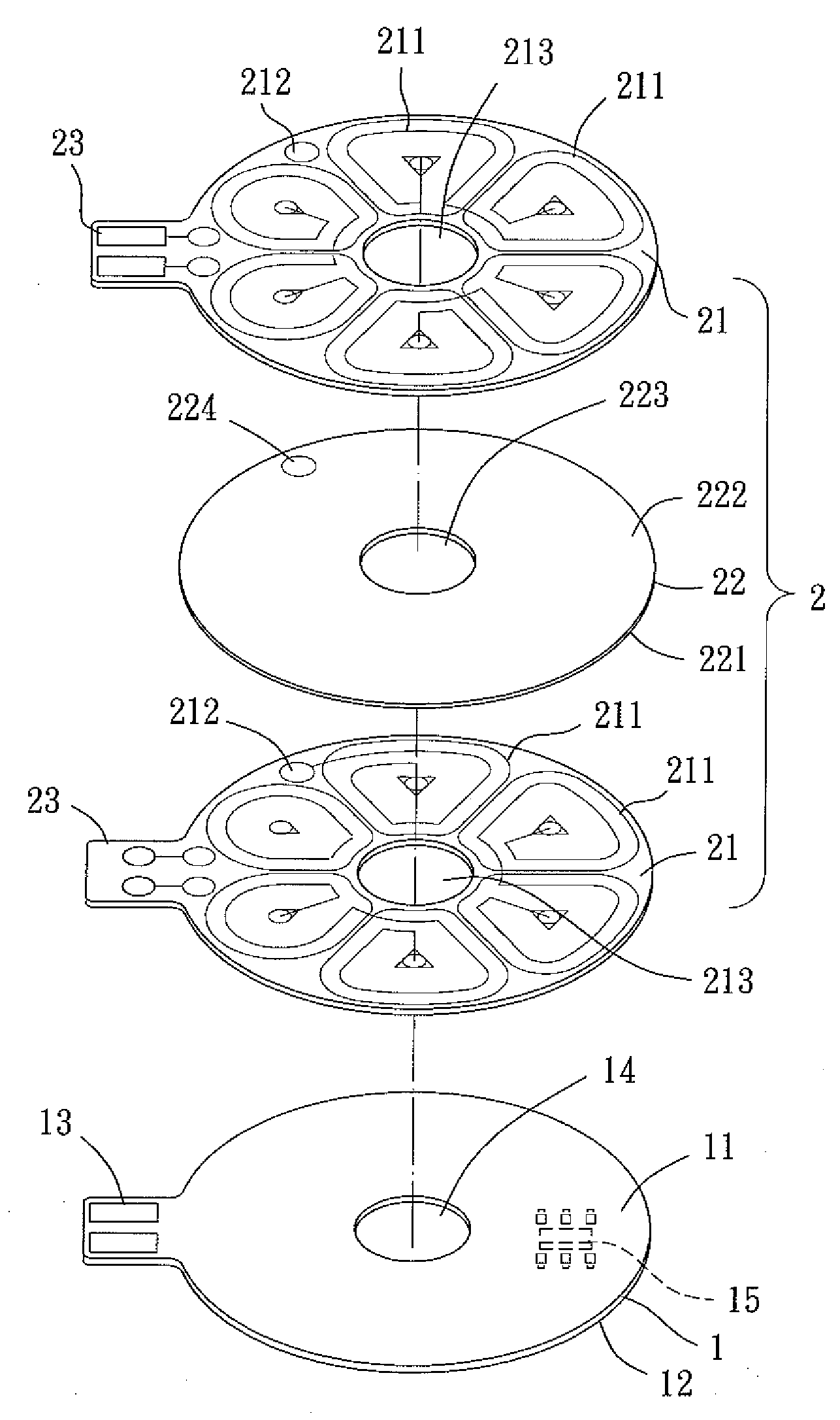
[0021]A motor stator according to the preferred teachings of the present invention is shown in FIG. 4. The motor stator includes a substrate 1 and a coil unit 2 coupled to a side of the substrate 1 to effectively reduce an overall axial height and a volume of the motor stator.

[0022]The substrate 1 can be a printed circuit board and includes first and second faces 11 and 12 spaced along an axis. The coil unit 2 is coupled to the first face 11 of the substrate 1 and includes a plurality of layout layers 21 each having a surface on which a plurality of coils 211 and a conductive portion 212 electrically connected to the coils 211 are formed. The layout layers 21 are stacked along the axis. An insulting layer 22 is provided between two adjacent layout layers 21. The conductive portions 212 of two adjacent layout layers 21 are electrically connected to each other. It can be appreciated that the surface of each layout layer 21 can include only one coil 211. Furthermore, the surface of eac...


PUM


Abstract

A coil unit for a motor stator includes a plurality of layout layers. At least one coil and a conductive portion electrically connected to the at least one coil are formed on a surface of each layout layer. The conductive portions of two adjacent layout layers are electrically connected to each other. An insulting layer is provided between two adjacent layout layers. The coil unit can be coupled to a face of a substrate to form a motor stator with reduced axial height and reduced volume.

Description

BACKGROUND OF THE INVENTION[0001]1. Field of the Invention[0002]The present invention relates to a coil unit for a motor stator and, more particularly, to a coil unit for reducing an axial height and a volume of a motor stator.[0003]2. Description of the Related Art[0004]FIG. 1 shows a conventional motor stator 8 including a plurality of silicon steel plates 81, two insulating sleeves 82, and a coil unit 83. Each silicon steel plate 81 includes a ring 811 and a plurality of supporting arms 812 extending radially outward from an outer periphery of the ring 811. A distal end of each supporting arm 812 forms a magnetic pole face 813. After the silicon steel plates 81 are stacked up, the insulating sleeves 82 are mounted to two ends of the stacked silicon steel plates 81. Each insulating sleeve 82 includes a plurality of extensions 821 corresponding to the supporting arms 812. The coil unit 83 includes a plurality of coils 831 wound around the respective supporting arms 812 and the resp...

Claims


Application Information

Patent Timeline
Patent Type & Authority Applications(United States)
IPC IPC(8): H02K3/26
CPCH02K3/26H02K5/225H02K3/47
Inventor HORNG, ALEXYIN, TSO-KUO
Owner SUNONWEALTH ELECTRIC MACHINE IND
Why Eureka
Try Eureka