Method and apparatus for current measurement in phase lines

a current measurement and phase line technology, applied in the direction of resistance/reactance/impedence, instruments, spectral/fourier analysis, etc., can solve the problems of two measurement errors caused by offsets, subject to certain aging effects, etc., and achieve the effect of improving current measuremen

Active Publication Date: 2011-03-10
ROBERT BOSCH GMBH
View PDF10 Cites 7 Cited by
  • Summary
  • Abstract
  • Description
  • Claims
  • Application Information

AI Technical Summary

Benefits of technology

to make improved current measurement possible.

Problems solved by technology

In the 1-shunt current measurement, two measurement errors caused by offsets can occur.
Moreover, they are subject to certain aging effects.

Method used


Image

  • Method and apparatus for current measurement in phase lines
  • Method and apparatus for current measurement in phase lines
  • Method and apparatus for current measurement in phase lines

Examples


Embodiment Construction

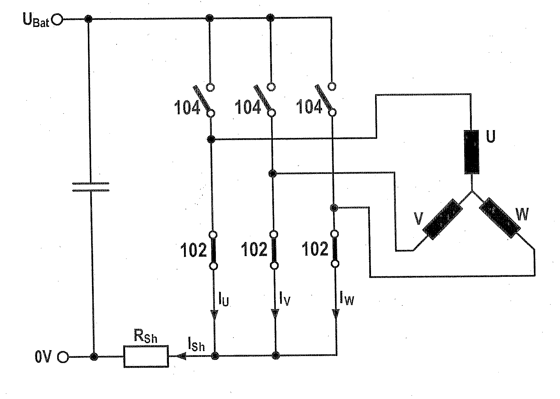
FIG. 1 shows a multiphase current network with a bridge circuit, in one exemplary embodiment of the present invention. The bridge circuit has three bridge branches. Each bridge branch has a first switch 102 and a second switch 104. The bridge circuit is embodied for triggering a three-phase consumer. For that purpose, a first bridge branch is connected to a first phase U of the consumer, a second bridge branch is connected to a second phase, and a third bridge branch is connected to a third phase. The consumer can be embodied as a three-phase asynchronous motor. The first switches 102 and the second switches 104 can be triggered by a control unit, not shown.

The bridge circuit is connected to a direct current circuit, which can be embodied as an intermediate current circuit. To that end, a first terminal of the bridge circuit is connected to a first voltage potential 0V via a resistor RSh, which can be embodied as a shunt. A second terminal of the bridge circuit is connected to a sec...


PUM


Abstract

In a method for current measurement in a multiphase current network, a conductive connection is produced between a plurality of the phases of the multiphase current network such that the plurality of the phases is short-circuited with one another. At a detection time, a current value flowing between the conductive connection and a first voltage potential is detected.

Description

FIELD OF THE INVENTIONThe invention relates to a method for current measurement in a multiphase current network in particular.PRIOR ARTA multiphase current network is used for instance to supply current to an electric motor. A current flowing in one phase of the multiphase current network can be measured by means of a low-impedance resistor (shunt). In so-called 1-shunt current measurement, the currents in the individual phases can be ascertained via a single shunt. However, measurement inaccuracies caused by offsets can occur.It is the object of the invention to make improved current measurement possible.DISCLOSURE OF THE INVENTIONThe present invention enables automatic measurement error compensation, which can be used for instance in a 1-shunt current measurement. The approach according to the invention is based on a definition of sampling times for ascertaining offset errors that occur. In the 1-shunt current measurement, two measurement errors caused by offsets can occur. These ...

Claims


Application Information

Patent Timeline
Patent Type & Authority Applications(United States)
IPC IPC(8): G01R23/16
CPCG01R19/0092H02M7/5395H02M2001/0009H02M7/53871H02M1/0009
Inventor FINKE, SVENKUEHN, TIMO
Owner ROBERT BOSCH GMBH
Why Eureka
Try Eureka