Method of Detecting a Fault Condition of a Load Control Device

a technology of load control device and fault condition, which is applied in the direction of pulse technique, power supply testing, instruments, etc., can solve the problems of semiconductor switch failure, undesirable conditions, and failure of semiconductor switch, and achieve the effect of reducing the number of failures and detecting the fault condition of the load control devi

Active Publication Date: 2011-03-10
LUTRON TECH CO LLC
View PDF11 Cites 44 Cited by
  • Summary
  • Abstract
  • Description
  • Claims
  • Application Information

AI Technical Summary

Benefits of technology

[0011]According to an embodiment of the present invention, a method of detecting a fault condition of a first semiconductor switch in a load control device operable to be electrically coupled between an alternating-current (AC) power source and a load for control of the load to an on state or an off state, the first semiconductor switch coupled in anti-series connection with a second semiconductor switch, the method comprising the steps of: measuring a first voltage across the first semiconductor switch during a first half cycle of the AC power so...

Problems solved by technology

Semiconductor switches, like many electrical components and devices, can be subject to failures.
The failure of the semiconductor switch may be the result of an exposure to over-voltage, over-current, and/or over-temperature conditions, or simply the expiration of a rated lifetime of the semiconductor switches.
For example, the asymmetric AC voltage may be caused when one of the semiconductor switches is rendered non-conductive during a portion of a positive half cycle but the other semiconductor switch is fully conductive during the entire negative half cycle as a result of failing in the shorted state.
The asymmetric AC voltage provided to the load results...

Method used


Image

  • Method of Detecting a Fault Condition of a Load Control Device
  • Method of Detecting a Fault Condition of a Load Control Device
  • Method of Detecting a Fault Condition of a Load Control Device

Examples


Embodiment Construction

[0026]The foregoing summary, as well as the following detailed description of the preferred embodiments, is better understood when read in conjunction with the appended drawings. For the purposes of illustrating the invention, there is shown in the drawings an embodiment that is presently preferred, in which like numerals represent similar parts throughout the several views of the drawings, it being understood, however, that the invention is not limited to the specific methods and instrumentalities disclosed.

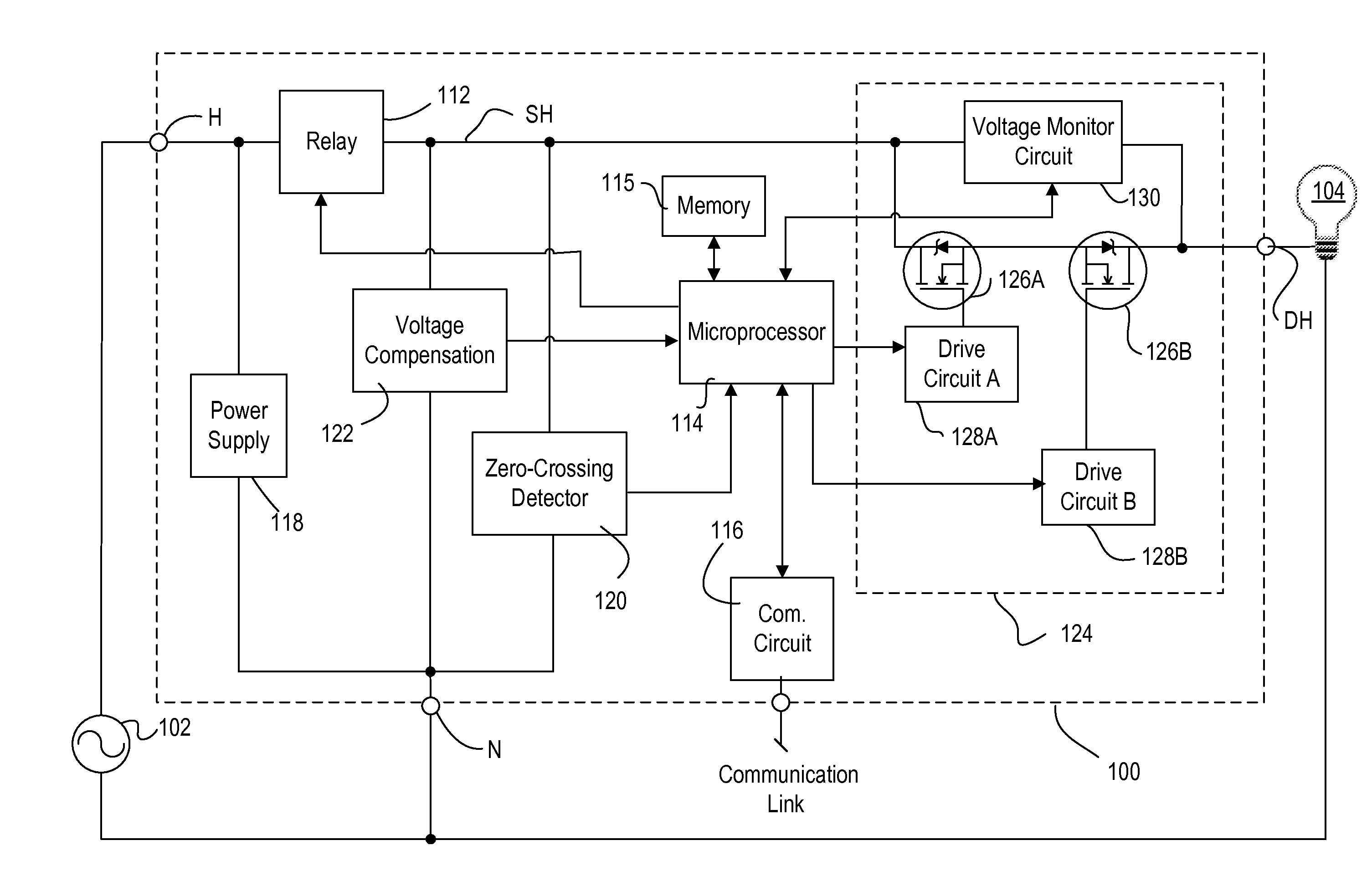
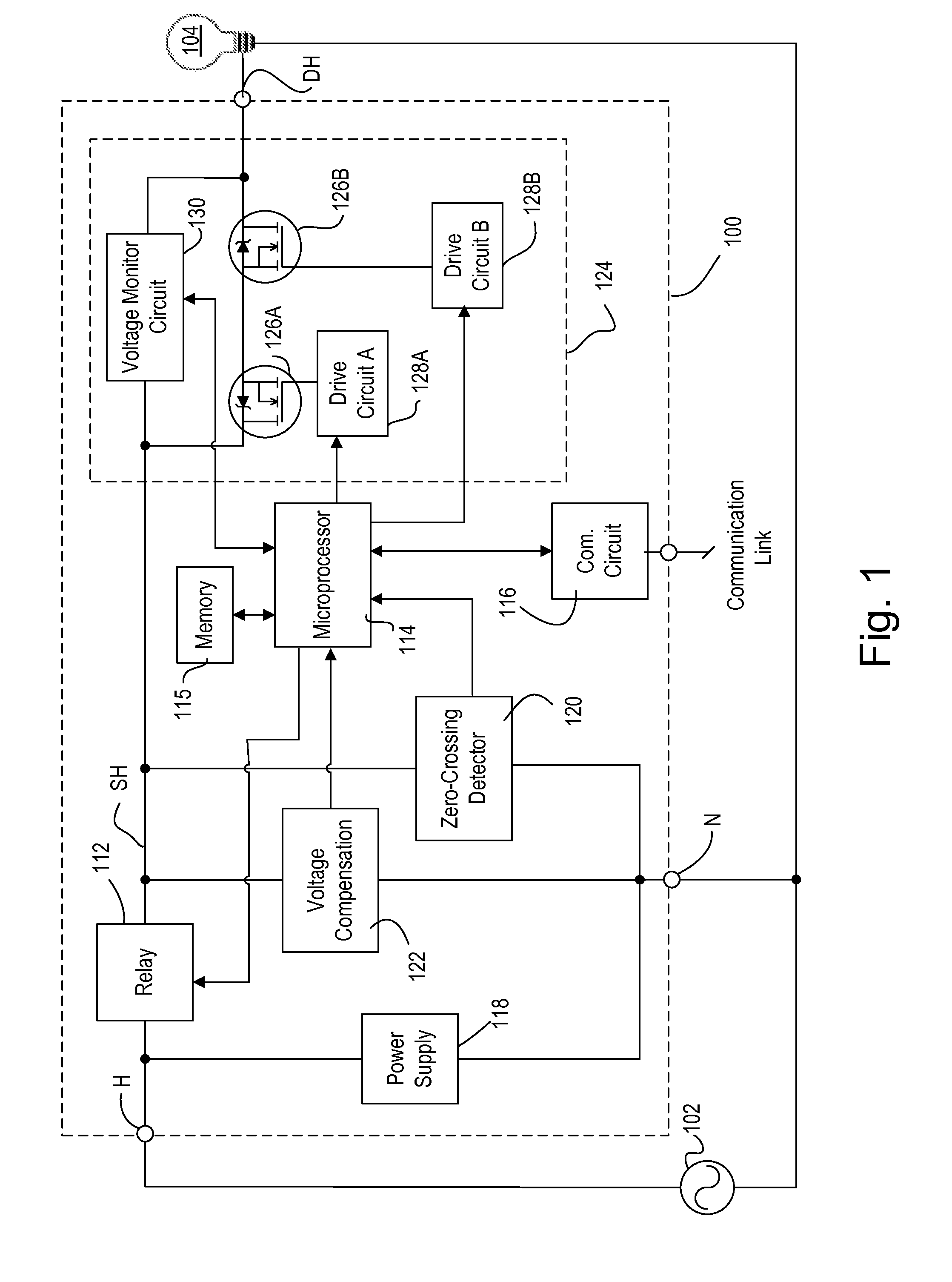
[0027]FIG. 1 is a simplified block diagram of a load control device 100 electrically coupled between a hot reference of an alternating current (AC) power source 102 (e.g., 120 V, 60 Hz) via a hot terminal (H) and a lighting load 104 via a dimmed hot terminal (DH). The lighting load 104 is coupled between the DH terminal and a neutral reference of the AC power source 102 and may comprise, for example, an incandescent lighting load, a low voltage lighting load including a magnetic...


PUM


Abstract

A load control device comprises a bidirectional semiconductor switch for controlling the amount of power delivered to an electrical load, and the bidirectional semiconductor switch further comprises two field effect transistors (FETs) in anti-series electrical connection. In the event that one of the FETs fails in a shorted state, and if the load control device is using a phase control dimming technique to control the load, the load control device may provide an asymmetric waveform to the electrical load. In order to determine whether this asymmetric waveform is present, a microprocessor of the load control device use voltage thresholds and/or offsets to monitor the voltage across the FETs. Thus, the microprocessor is operable to detect a fault condition of the load control device wherein the fault condition may comprise an asymmetry condition, or more particularly, a failure condition of one of the FETs.

Description

BACKGROUND OF THE INVENTION[0001]1. Field of the Invention[0002]The present invention relates to a load control device comprising a bidirectional semiconductor switch for controlling the amount of power delivered to an electrical load, and more specifically, to a method of detecting a fault condition of the load control device, in particular, a failure condition of the bidirectional semiconductor switch.[0003]2. Description of the Related Art[0004]Bidirectional semiconductor switches are typically used in various load control devices to control the amount of power provided from an alternating current (AC) power source to a load, such as a lighting load. A bidirectional semiconductor switch may comprise one semiconductor switch such as a field effect transistor (FET) within a full-wave rectifying bridge or a triac; or two semiconductor switches, such as two FETs or two insulated gate bipolar transistors (IGBTs), coupled in anti-series electrical connection, or two silicon-controlled ...

Claims


Application Information

Patent Timeline
IPC IPC(8): H02H3/00G01R31/08
CPCG01R31/3277G01R31/42Y02B20/146H02M5/293H05B39/044H02M1/32Y02B20/00
Inventor ORCHOWSKI, NEIL
Owner LUTRON TECH CO LLC
Why Eureka
Try Eureka