Methods and arrangement for plasma dechuck optimization based on coupling of plasma signaling to substrate position and potential

a plasma signaling and optimization method technology, applied in the direction of basic electric elements, semiconductor/solid-state device manufacturing, electrical equipment, etc., can solve the problems of processing system being taken, part of the substrate to break apart, and damage to the substra

Active Publication Date: 2011-03-10
LAM RES CORP
View PDF23 Cites 8 Cited by
  • Summary
  • Abstract
  • Description
  • Claims
  • Application Information

AI Technical Summary

Benefits of technology

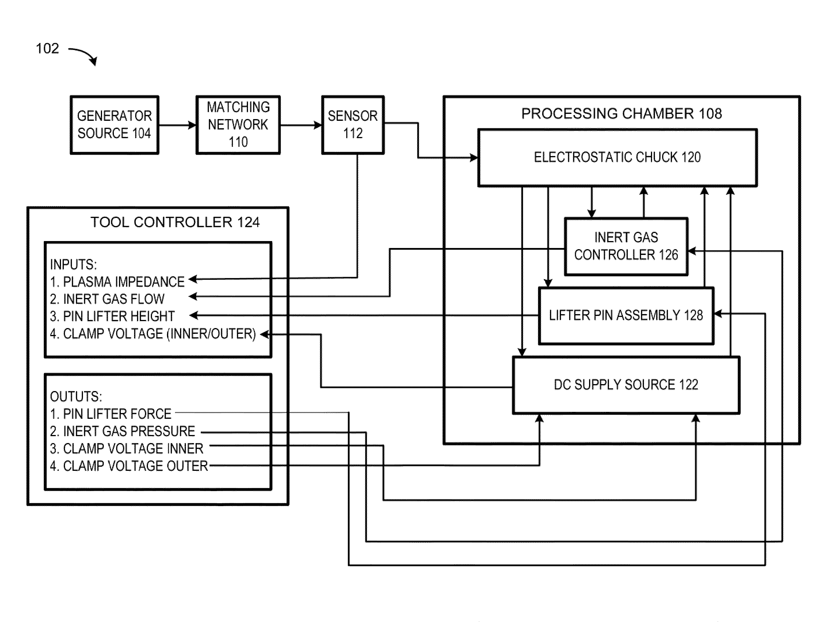
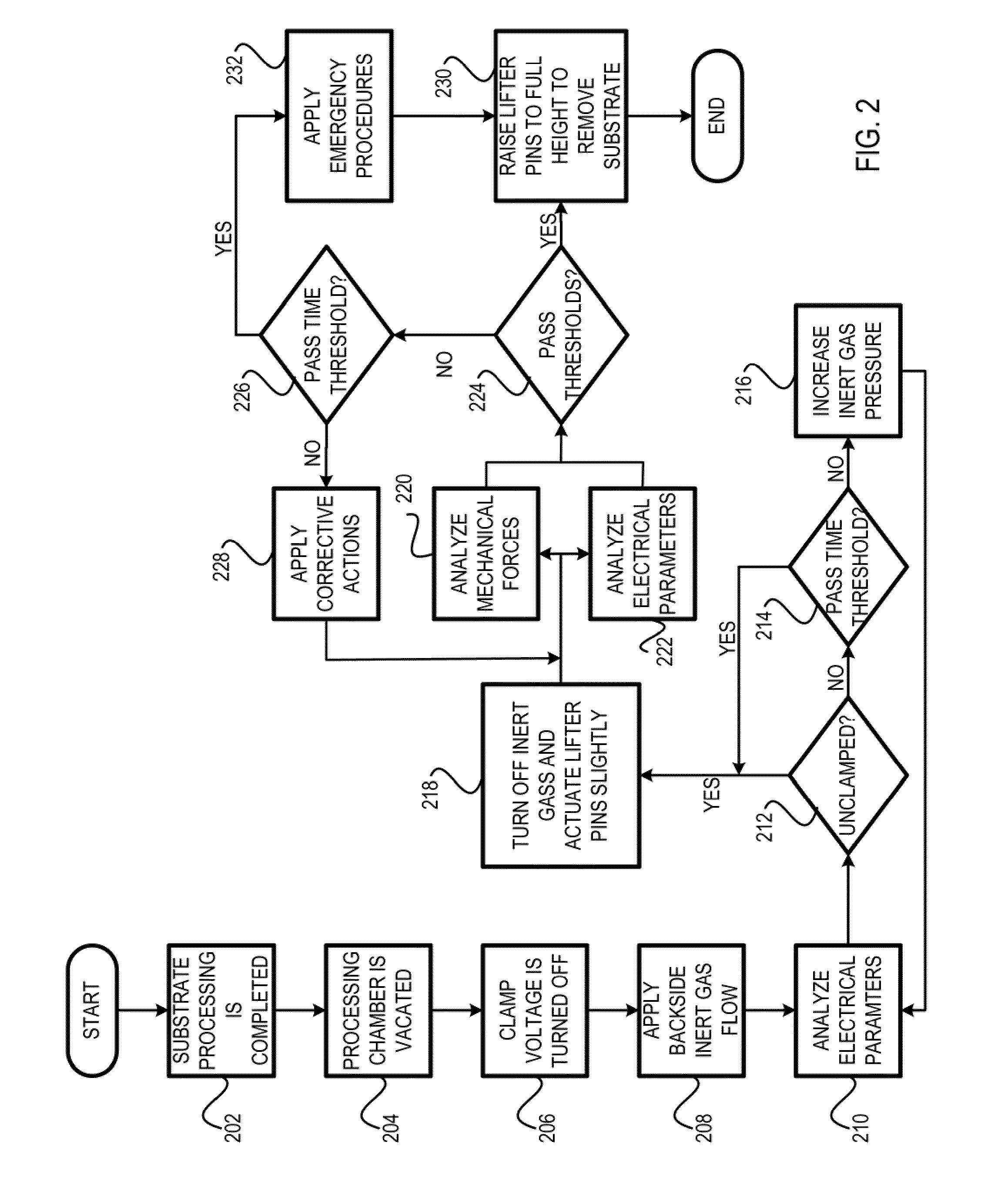
[0017]The invention relates, in an embodiment, to a method for optimizing a dechuck sequence, which includes mechanically removing a substrate from a lower electrode in a processing chamber of a plasma processing system. The method includes performing an initial analysis. The initial analysis includes analyzing a first set of electrical characteristic data of a plasma, wherein the plasma is formed over the substrate during the dechuck sequence. The initial analysis also includes comparing the first set of electrical characteristic data against a set of electrical characteristic threshold values. The initial analysis further includes, if the first set of electrical characteristic data traverses the set of electrical characteristic threshold values, turning off inert gas. The method also includes raising the lifter pins from the lower electrode to move the substrate in an upward direction, wherein the lifter pins are not raised to a maximum height. The method further includes performing a mechanical and electrical analysis. The mechanical and electrical analysis includes analyzing a first set of mechanical data, wherein the set of mechanical data includes an amount of force exerted by the lifter pins. The mechanical and electrical analysis also includes analyzing a second set of electrical characteristic data. The mechanical and electrical analysis further includes comparing the first set of mechanical data to a set of mechanical threshold values and the second set of electrical characteristic data to the set of electrical characteristic threshold values. The mechanical and electrical analysis yet also includes, if the first set of mechanical data traverses the set of mechanical threshold values and the second set of electrical characteristic data traverses the set of electrical characteristic threshold values, removing the substrate from the lower electrode since a substrate-released event has occurred.

Problems solved by technology

If the electrostatic charge has not been satisfactorily removed, partial sticking may exist resulting in partial substrate hinging to the surface of the lower electrode, thereby causing part of the substrate to break apart when the lifter pins is pushed upward from the lower electrode.
The partial sticking may not only damage the substrate but the debris caused by substrate cracking may also require the plasma processing system to be taken offline for chamber cleaning.
In addition, if the electrostatic charge has not been satisfactorily discharged, enough charge may still exist on the substrate to cause arcing between the substrate and the robot arm when the robot arm tries to remove the substrate from the processing chamber.
Arcing is an uncontrolled event that may cause undesirable results, such as damage to devices on the substrate and / or the robot arm.
Unfortunately, both methods of dechucking (at zero volts and at a bias voltage of reverse polarity) still do not always provide a safe and efficient manner of releasing the substrate.
However, the specified time period method does not provide an early-detection method for identifying when the substrate may be safely removed from the lower electrode.
As a result, throughput is negatively impacted as time is wasted while the unhinged substrate remains in the processing chamber for the entire specified time period before the unhinged substrate may be removed from the chamber.
Also, the existence of the dechuck plasma in the processing chamber for the additional (and unnecessary) time may also contribute to the premature degradation of the chamber components and / or unwanted etching of the substrate.
In other cases, the electrostatic charge may not have been sufficiently discharged after the specified time period has elapsed.
As a result, the attempt to remove the hinged substrate may cause the substrate to break.
Accordingly, the force exerted on the substrate may cause the substrate to shift away from the process center, thereby causing the substrate to be improperly aligned for the next recipe step.
In addition, the residual electrostatic charge on the substrate may cause arcing between the substrate and the robot arm, thereby causing damage to the devices on the substrate and / or the robot arm.
However, the aforementioned methods tend to be time consuming and cumbersome.
For example, in one case, only one or two parameters may be adjusted at any one point in time since adjusting too many parameters at once may cause an uncontrolled dechuck sequence.
Given the high degree of variability, monitoring based on mechanical values (such as helium flow, induced pressure, and or force of lifter pins) is insufficient in optimizing the dechuck sequence since the mechanical values do not accurately and / or adequately characterize the actual electrostatic charges between the substrate and the lower electrode.
Thus, isolated pockets may exist in which the electrostatic charge has not been sufficiently removed.
As a result, isolated hinging may still occurs resulting in damage to the substrate when the substrate is separated from the lower electrode.
In addition, since none of the monitored mechanical values accurately characterizes the actual electrostatic charge between the substrate and the lower electrode, a residual amount of charge may still exist on the substrate even though the substrate may be successfully lifted from the lower electrode.
As a result, arcing may still occur between the substrate and the robot arm, resulting in damages to devices on the substrate and / or the robot arm.

Method used


Image

  • Methods and arrangement for plasma dechuck optimization based on coupling of plasma signaling to substrate position and potential
  • Methods and arrangement for plasma dechuck optimization based on coupling of plasma signaling to substrate position and potential
  • Methods and arrangement for plasma dechuck optimization based on coupling of plasma signaling to substrate position and potential

Examples


Embodiment Construction

[0029]The present invention will now be described in detail with reference to a few embodiments thereof as illustrated in the accompanying drawings. In the following description, numerous specific details are set forth in order to provide a thorough understanding of the present invention. It will be apparent, however, to one skilled in the art, that the present invention may be practiced without some or all of these specific details. In other instances, well known process steps and / or structures have not been described in detail in order to not unnecessarily obscure the present invention.

[0030]Various embodiments are described hereinbelow, including methods and techniques. It should be kept in mind that the invention might also cover articles of manufacture that includes a computer readable medium on which computer-readable instructions for carrying out embodiments of the inventive technique are stored. The computer readable medium may include, for example, semiconductor, magnetic, ...


PUM


Abstract

A method for optimizing a dechuck sequence, which includes removing a substrate from a lower electrode. The method includes performing an initial analysis to determine if a first set of electrical characteristic data of a plasma formed during the dechuck sequence traverses a threshold values. If so, turning off the inert gas. The method also includes raising the lifter pins slightly from the lower electrode to move the substrate in an upward direction. The method further includes performing a mechanical and electrical analysis, which includes comparing a first set of mechanical data, which includes an amount of force exerted by the lifter pins, against a threshold value. The mechanical and electrical analysis also includes comparing a second set of electrical characteristic data against a threshold value. If both traverse the respective threshold value, removes the substrate from the lower electrode since a substrate-released event has occurred.

Description

CROSS REFERENCE TO RELATED APPLICATIONS[0001]The present invention is related to the following application(s), all of which are incorporated herein by reference:[0002]Commonly assigned application entitled “Methods and Arrangement For Detecting A Substrate-Released Event Within A Plasma Processing Chamber,” filed on even date herewith by Valcore et al. (Attorney Docket Number P1871 / LMRX-P177).BACKGROUND OF THE INVENTION[0003]Advances in plasma processing have facilitated growth in the semiconductor industry. In tile competitive semiconductor industry, a manufacturer may gain a competitive edge if the manufacturer has the ability to maximize throughput and / or to produce quality devices at a lower cost. One method for controlling throughput is to control the dechuck sequence to optimize the substrate-release time.[0004]During substrate processing, a substrate is usually clamped to a lower electrode (such as an electrostatic chuck). Clamping may be performed by applying a direct curren...

Claims


Application Information

Patent Timeline
Patent Type & Authority Applications(United States)
IPC IPC(8): H01T23/00
CPCH01L21/6831H01L21/67069
Inventor VALCORE, JR., JOHN C.ULLAL, SAURABHBYUN, DANIELSANTOS, EDMAKHRATCHEV, KONSTANTIN
Owner LAM RES CORP
Why Eureka
Try Eureka