Textile-based magnetic field interface clothes and mobile terminal in wearable computing system
a technology of magnetic field and mobile terminal, which is applied in the direction of near-field systems using receivers, transducer details, protective garments, etc., can solve the problems of inconvenient socket attachment and detachment, radio is relatively weak, user is required to use waterproof treatment on the socket, etc., to minimize the effect of signal attenuation phenomenon, low power structure and efficient increase of signal transmission efficiency
- Summary
- Abstract
- Description
- Claims
- Application Information
AI Technical Summary
Benefits of technology
Problems solved by technology
Method used
Image

Examples
first embodiment
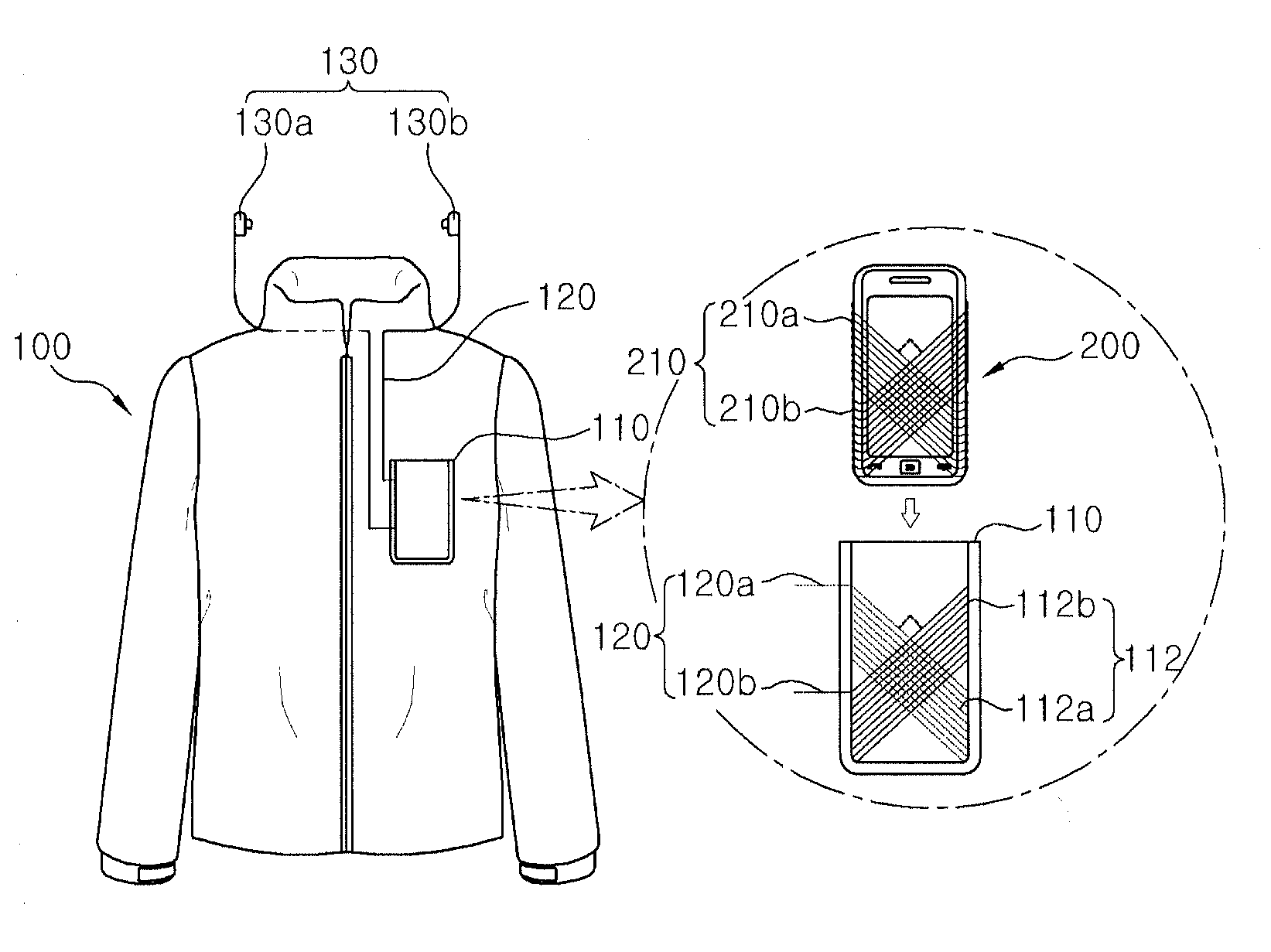
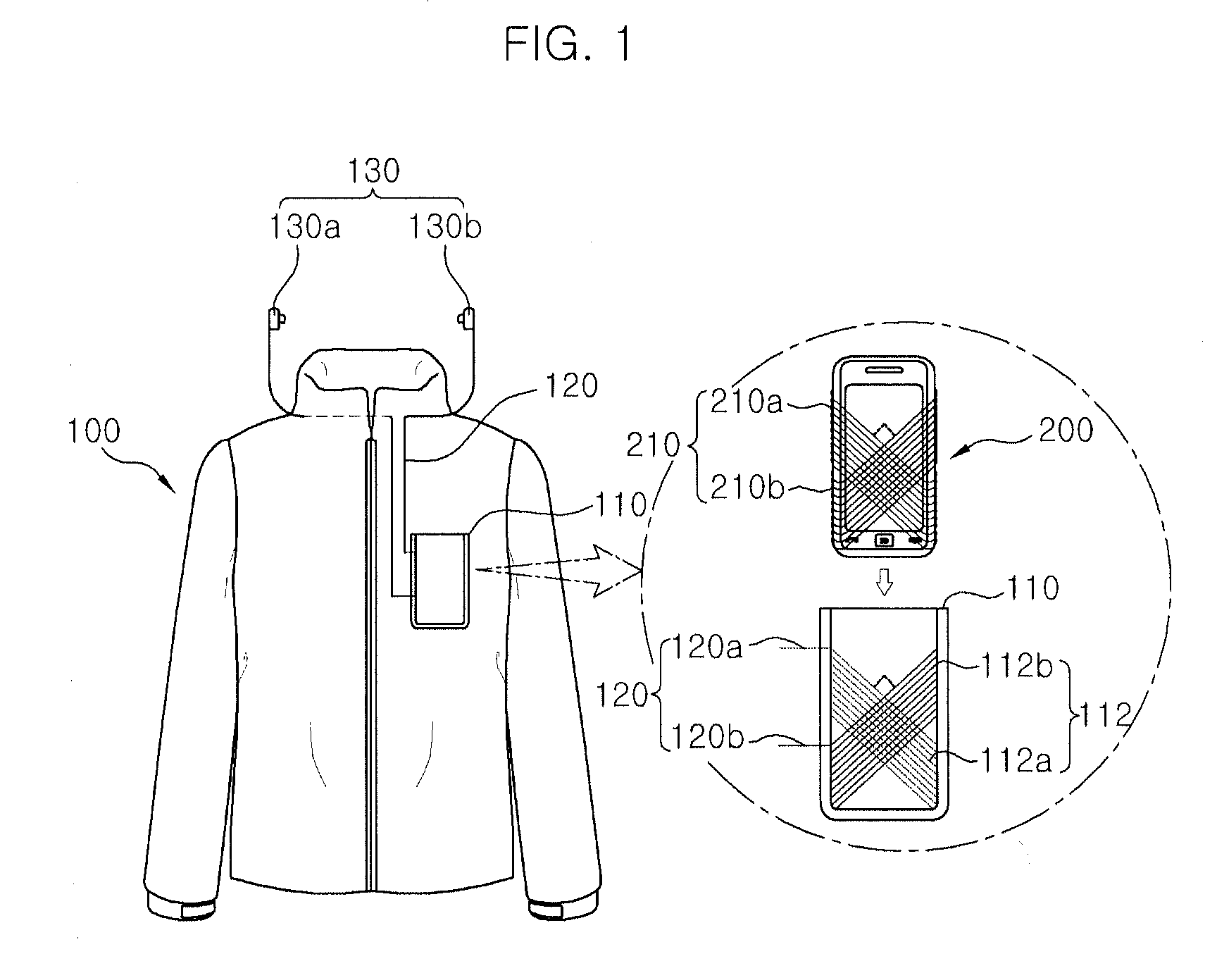
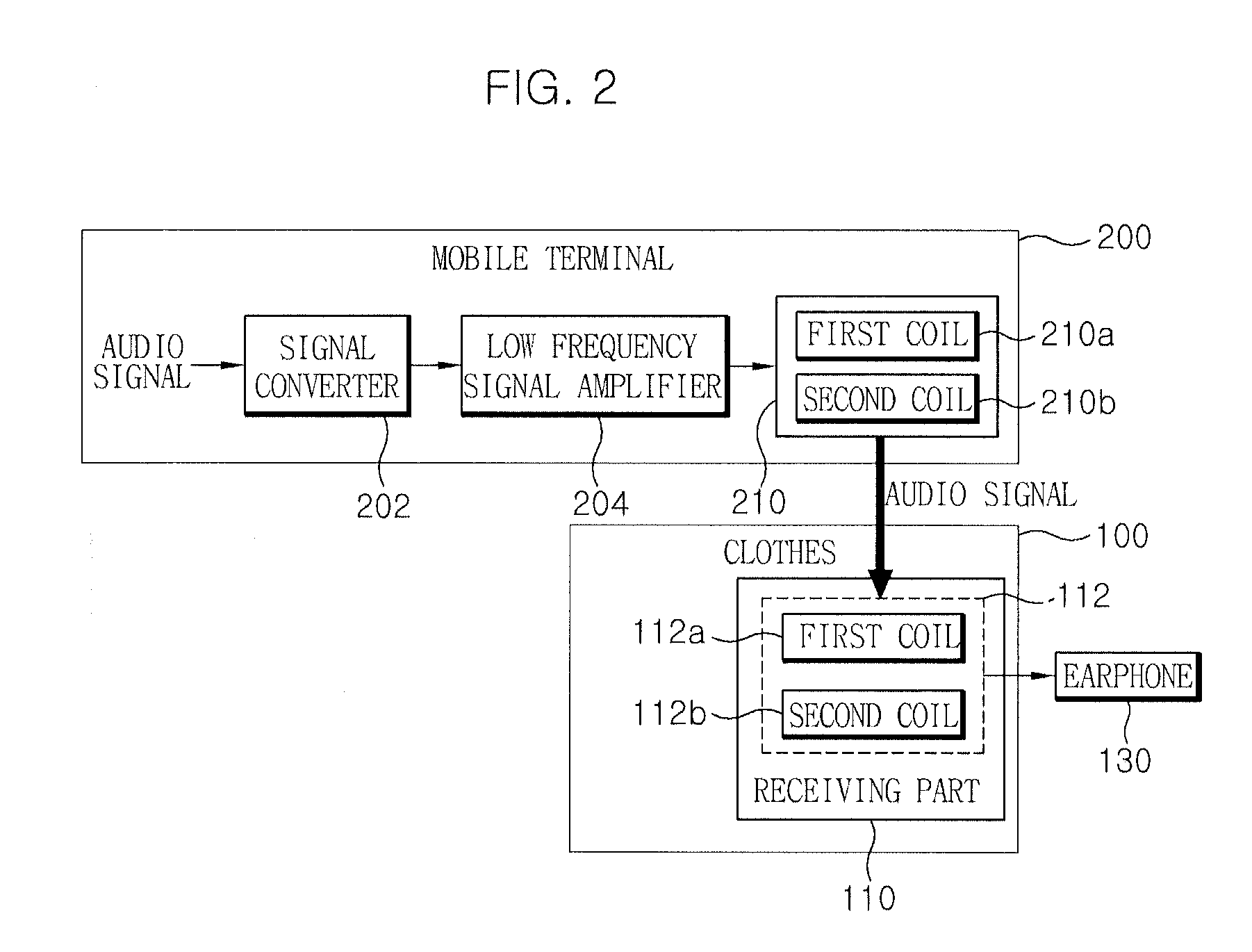
[0052]FIG. 1 is an exemplified diagram for explaining a wearable computing system according to a first embodiment of the present invention. FIG. 2 is a block diagram for explaining in detail a configuration of textile-based magnetic field interface clothes and a mobile terminal in the wearable computing system of FIG. 1.
[0053]The wearable computing system according to the first embodiment of the present invention includes textile-based magnetic field interface clothes 100 (hereinafter, referred to as ‘clothes’) and a mobile terminal 200.
[0054]Referring to FIGS. 1 and 2, the clothes 100 are provided with a receiving part (for example, a pocket) and the mobile terminal 200 of the user is received in the receiving part 110. In this case, it is preferable that a size of the receiving part 110 is the same as that of the mobile terminal 200 or the mobile terminal 200 is formed to have only a slight gap. This is to more stably perform magnetic field communication by increasing a flux densi...
second embodiment
[0067]FIG. 3 is an exemplified diagram for explaining a wearable computing system according to a second embodiment of the present invention. FIG. 4 is a block diagram for explaining in detail a configuration of textile-based magnetic field interface clothes and a mobile terminal in the wearable computing system of FIG. 3.
[0068]The wearable computing system according to the second embodiment of the present invention includes textile-based magnetic field interface clothes 300 (hereinafter, referred to as ‘clothes’) and a mobile terminal 350.
[0069]Referring to FIGS. 3 and 4, the clothes 300 are provided with a receiving part 310 and the mobile terminal 350 of the user is received in the receiving part 310. In this case, it is preferable that a size of the receiving part 310 is the same as that of the mobile terminal 350 or the mobile terminal 350 is formed to have only a slight gap. This is to more stably perform magnetic field communication by increasing a flux density when the mobile...
third embodiment
[0082]FIG. 5 is an exemplified diagram for explaining a wearable computing system according to a third embodiment of the present invention. FIG. 6 is a block diagram for explaining in detail a configuration of textile-based magnetic field interface clothes and a mobile terminal in the wearable computing system of FIG. 5.
[0083]The wearable computing system according to the third embodiment of the present invention includes textile-based magnetic field interface clothes 400 (hereinafter, referred to as ‘clothes’) and a mobile terminal 450.
[0084]Comparing the third embodiment with the second embodiment, a control signal generator 440 in the third embodiment does not include a separate power supply unit (for example, the power supply unit of FIG. 4), unlike the control signal generator 340 in the second embodiment. In other words, the control signal generator 440 of FIG. 6 is operated by being supplied with power from the portable terminal 400 by using the magnetic induction scheme, whi...
PUM
 Abstract
Description
Claims
Application Information
 - R&D
- Intellectual Property
- Life Sciences
- Materials
- Tech Scout
- Unparalleled Data Quality
- Higher Quality Content
- 60% Fewer Hallucinations
Browse by: Latest US Patents, China's latest patents, Technical Efficacy Thesaurus, Application Domain, Technology Topic, Popular Technical Reports.
© 2025 PatSnap. All rights reserved.Legal|Privacy policy|Modern Slavery Act Transparency Statement|Sitemap|About US| Contact US: help@patsnap.com