
Prismatic cell

a cell and cell body technology, applied in secondary cell details, sustainable manufacturing/processing, batteries, etc., can solve the problems of wrinkling, bending (buckling), tearing, and the like in the outer covering, and achieve the effect of convenient insertion into the cell case and wrinkling, convenient use, and increased capacity

Active Publication Date: 2011-03-10
TOYOTA JIDOSHA KK
View PDF5 Cites 23 Cited by
  • Summary
  • Abstract
  • Description
  • Claims
  • Application Information

AI Technical Summary

Benefits of technology

[0006]The present invention was conceived in light of this, and its main object is to provide a prismatic cell comprising a flat electrode unit and an outer covering of the same shape, which is easy to insert into a cell case, with good insulation ensured between the electrode unit and the cell case in this cell.

Problems solved by technology

However, with a conventional cell constitution, since the outer covering is in the form of a box having corners, it was difficult to insert the outer covering (and the electrode unit) into the cell case.
For example, if the corners (the four corners) in a plan view of the cell case had a rounded shape (R-shape), the corners of the outer covering interfered with the corners of the cell case, making it difficult to insert the electrode unit housed in the outer covering.
Also, with an electrode unit constituted in this way, during insertion into the cell case, in some cases there was the risk of wrinkling, bending (buckling), tearing, or the like in the outer covering.
If this should happen, the insulating function of the outer covering is impaired, and there is the risk that insulation between the electrode unit and the cell case will be lost and an internal short will occur, so wrinkling and so forth of the outer covering needs to be prevented.

Method used


Image

  • Prismatic cell
  • Prismatic cell
  • Prismatic cell

Examples


Embodiment Construction

[0029]Preferred embodiments of the present invention will now be described through reference to the drawings. Matters that are necessary for working the present invention, other than matters specifically mentioned in this Specification (such as general technology related to the construction of cells, the constitution of cells and their construction procedures, and so on) can be ascertained as design matters for a person skilled in the art on the basis of prior art in this field. The present invention can be worked on the basis of technical common knowledge in this field and the content of the disclosure in this Specification.

[0030]The term “cell” in this Specification refers to a storage device from which a specific electrical energy can be taken off, and is not limited to any specific collecting mechanism (electrode unit or electrolyte constitution). Specifically, it is a term that encompasses so-called chemical cells such as lithium secondary cells, lithium ion cells, nickel hydro...


PUM


Abstract

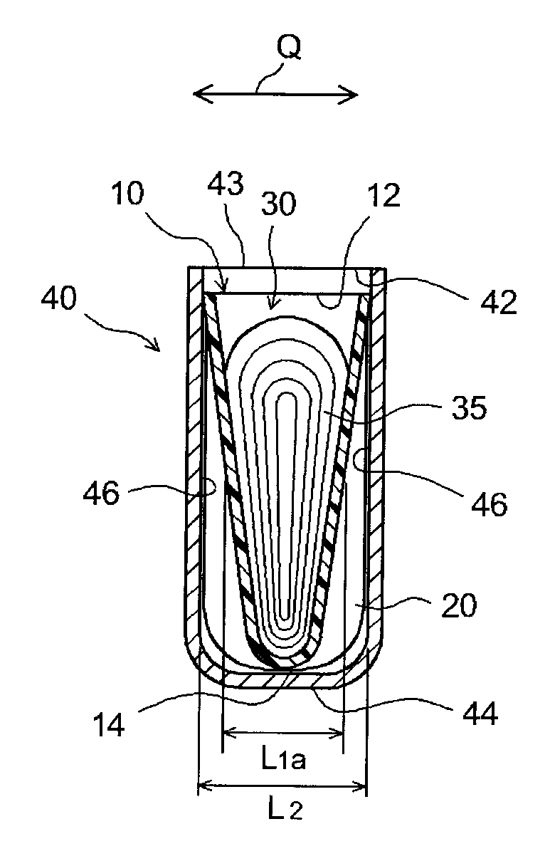
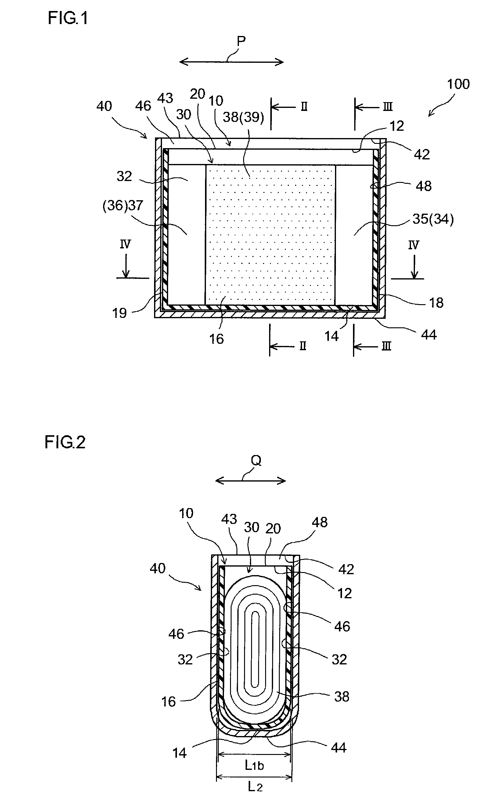
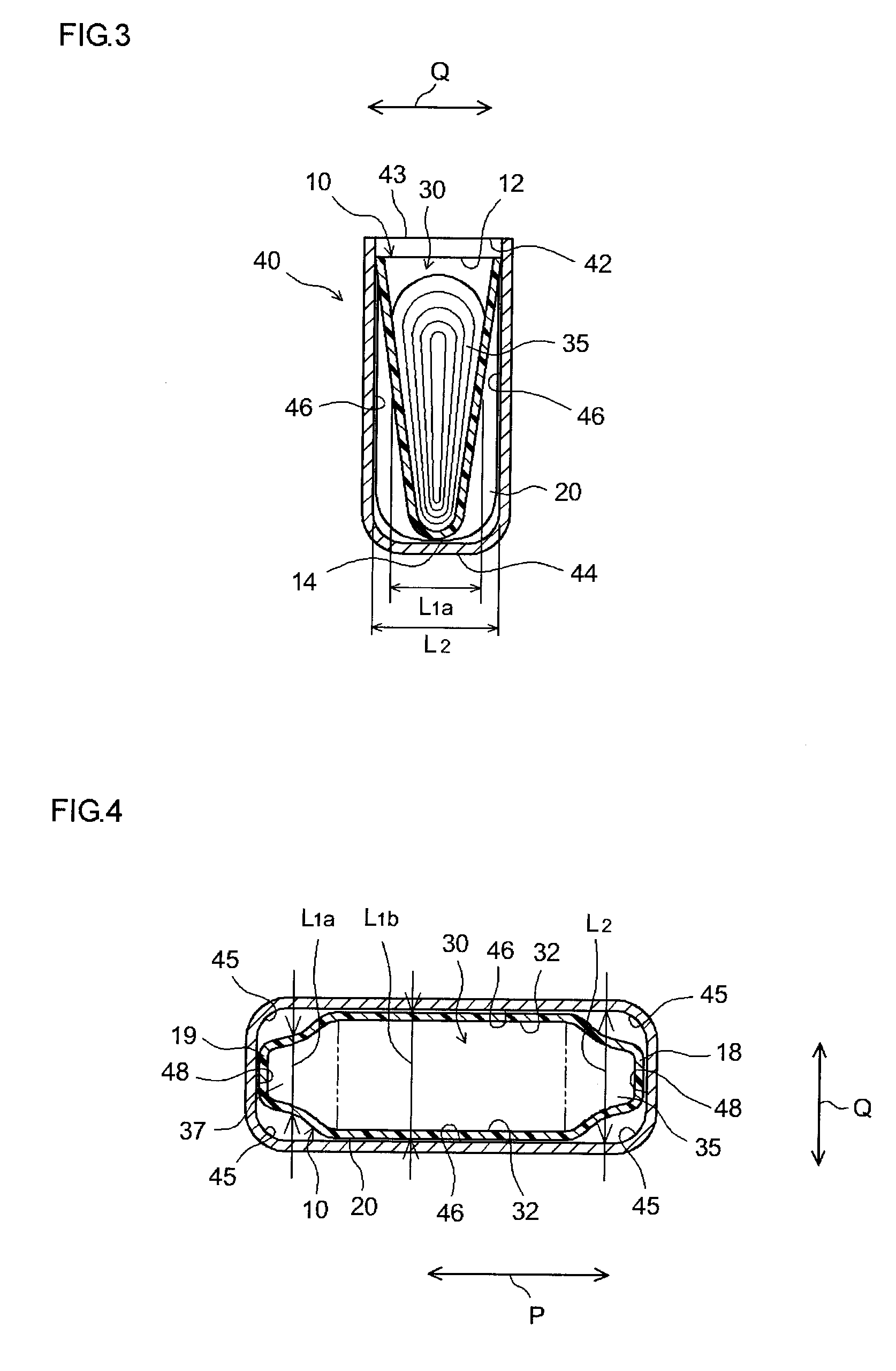
This cell comprises an electrode unit 30, a cell case 40 in which the electrode unit 30 is housed, and an insulated outer covering 20 located between the electrode unit 30 and the cell case 40. The electrode unit 30 is housed, from an opening 43 formed at an upper end 42 of the cell case 40, in the cell case 40 in a lateral direction in which a positive electrode collection component 35 and a negative electrode collection component are disposed along from the upper end 42 to the bottom 44 at both ends of a wide face 46 of the cell case 40, and is disposed inside the outer covering 20, to constitute an electrode insertion unit 10 along with the outer covering 20. Here, the thickness (L1a) of the electrode insertion unit 10 at both ends in the lateral direction steadily decreases from the upper end 42 toward the bottom 44 of the cell case 40.

Description

TECHNICAL FIELD[0001]The present invention relates to a prismatic cell comprising an electrode unit with a flat shape and a cell case formed in a box shape corresponding to the shape of the electrode unit. More particularly, the present invention relates to the structure of a prismatic cell that is favorable for installation in vehicles. This application claims priority on the basis of Japanese Patent Application No. 2008-126346 filed on May 13, 2008, the content of which is incorporated herein by reference in its entirety.BACKGROUND ART[0002]In recent years there has been growing demand for lithium ion cells, nickel hydrogen cells, and other secondary cells for use as power supplies installed in vehicles, or as power supplies for personal computers and portable terminals. In particular, lithium ion cells, which are lightweight and offer high energy density, hold promise for favorable use as high-output power supplies installed in vehicles. With this type of cell, a known cell struc...

Claims


Application Information

Patent Timeline
IPC IPC(8): H01M10/02H01M10/04H01M10/0587H01M50/103H01M50/119
CPCH01M2/0202H01M2/0277H01M2/1072Y02E60/122H01M10/0587H01M2002/0205H01M10/0525Y02E60/10Y02P70/50H01M50/103H01M50/119H01M2220/20
Inventor KAWASE, SATOMIMAKINO, TOMONORI
Owner TOYOTA JIDOSHA KK
Learn More