Method for slicing workpiece

a workpiece and workpiece technology, applied in the field of slicing workpieces, can solve the problems of heat generation, workpiece thermal expansion, etc., and achieve the effect of slicing straightly, preventing inflection of slicing trajectory, and sliced well

Active Publication Date: 2011-03-10
SHIN-ETSU HANDOTAI CO LTD
View PDF4 Cites 4 Cited by
  • Summary
  • Abstract
  • Description
  • Claims
  • Application Information

AI Technical Summary

Benefits of technology

[0019]As described above, when the workpiece is sliced with the workpiece inclined in the direction defined in the present invention according to the method for slicing a workpiece of the present invention, the inflection of the slicing trajectory in the opposite direction to the inflection of the slicing trajectory of the workpiece due to the expansion in an axial direction of wire guides are made occur, the inflections caused by two factors are thereby offset, and the workpiece can be therefore sliced straightly. That is to say, the slicing is started at the deliberately moved position of the wire by slicing the workpiece with it axially inclined so that the inflection of the slicing trajectory due to the force acting to put the wire back to the original position during slicing occurs in the opposite direction to the side where the wire guides are to be axially expanded. The slicing can be thereby performed well in which the inflection of the slicing trajectory is prevented, and it can be sliced into the wafers having improved Warp. In addition, a conventional apparatus can be basically used, any special devices are not necessary, and it can be therefore sliced well at low cost.

Problems solved by technology

Friction that occurs in this case causes generation of heat at a slicing portion and thereby the workpiece is thermally expanded during slicing.
There arises a problem that this inflection of the slicing trajectory is detected as Warp in a shape measurement after wafer processing.
However, an amount of the improvement is insufficient.

Method used


Image

  • Method for slicing workpiece
  • Method for slicing workpiece
  • Method for slicing workpiece

Examples


example 1

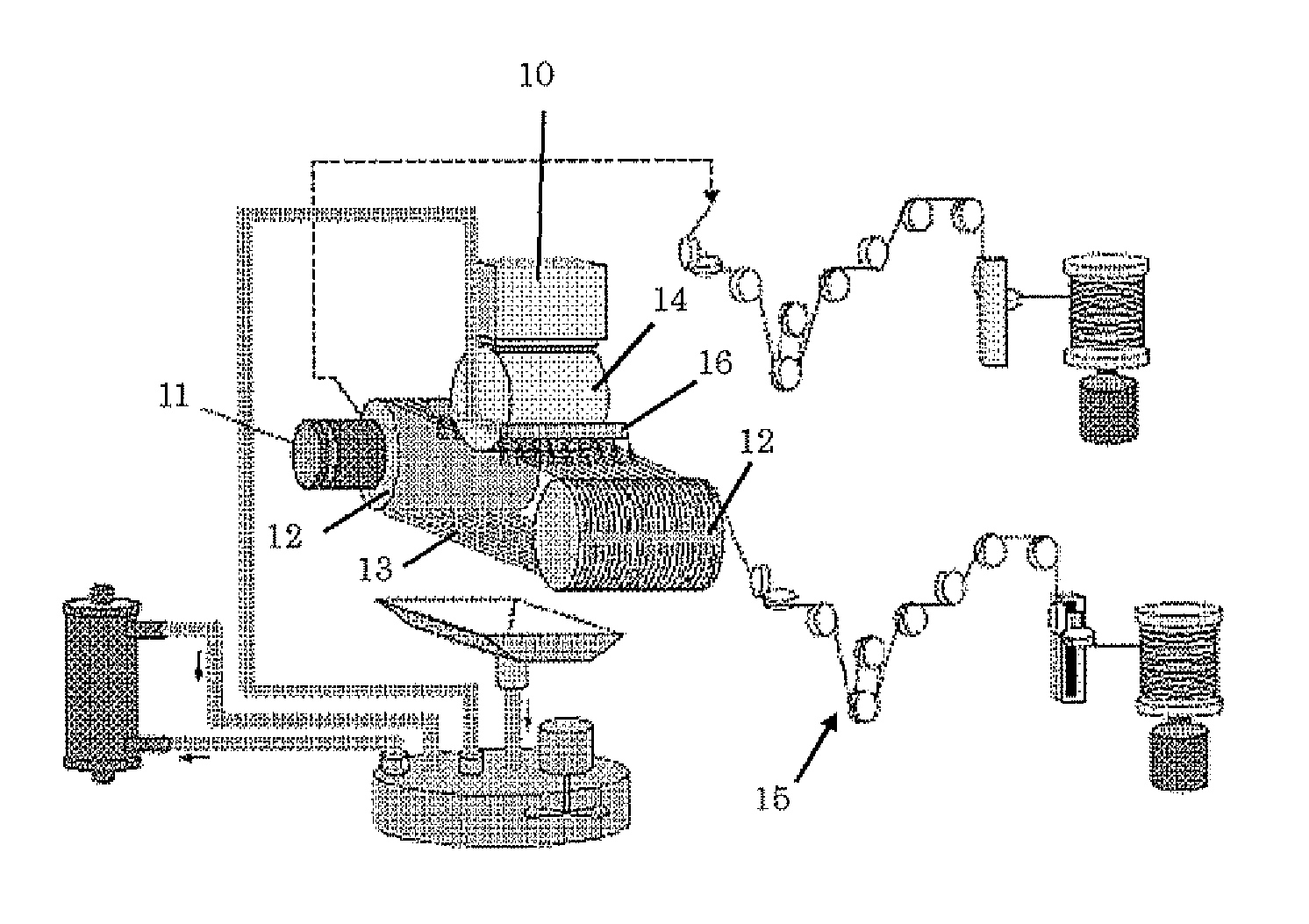
[0051]First, the wire saw apparatus as shown in FIG. 4 was used to slice a silicon ingot (a workpiece) having a diameter of 300 mm and an axial length of 300 mm in slicing conditions shown in Table 1. The supply temperature of the slurry was controlled to be a constant temperature of 23° C. from the start of slicing to the end of slicing.

TABLE 1SLICING CONDITIONSWORKPIECEINGOT DIAMETERø 300 mmWIREWIRE DIAMETER160 μmWIRE TENSION2.5 kgfNEW WIRE LINE 100 m / minSUPPLY AMOUNTWIRE REVERSAL 60 sCYCLEWIRE TRAVELING AVERAGE 500 m / minSPEEDSLURRYABRASIVE GRAINGC# 1000ABRASIVE GRAIN 50:50 CONCENTRATION(WEIGHT RATIO)(COOLANT: ABRASIVE GRAIN)

[0052]The workpiece was fixed in such a manner that a resin slice base was fixed by adhering to an upper surface of a metal workpiece holder, and the workpiece was adhered onto the resin slice base. When the workpiece was set to the wire saw apparatus, a set of the metal workpiece holder, the resin slice base, and the workpiece, which was fixed by these adhesi...

example 2

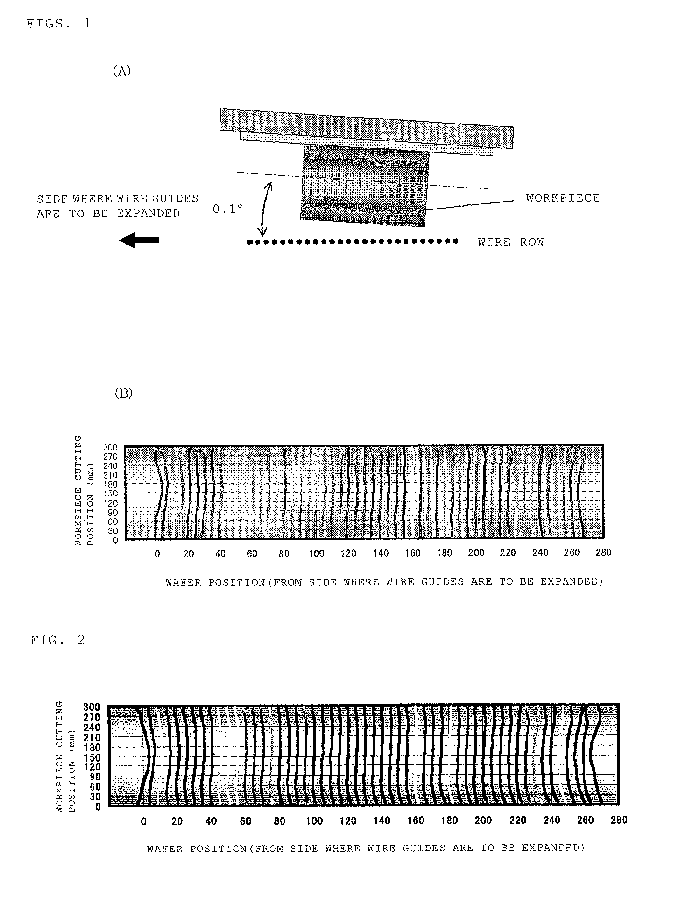
[0057]The slicing trajectory shown in FIG. 2 reveals that when one end face of a wire guide (a side of a horizontal axis scale of 280 in FIG. 2) is set as a reference position, the wire guide of the wire saw apparatus used in Example 1 was axially expanded in the direction of the other end face (a side of a horizontal axis scale of zero in FIG. 2).

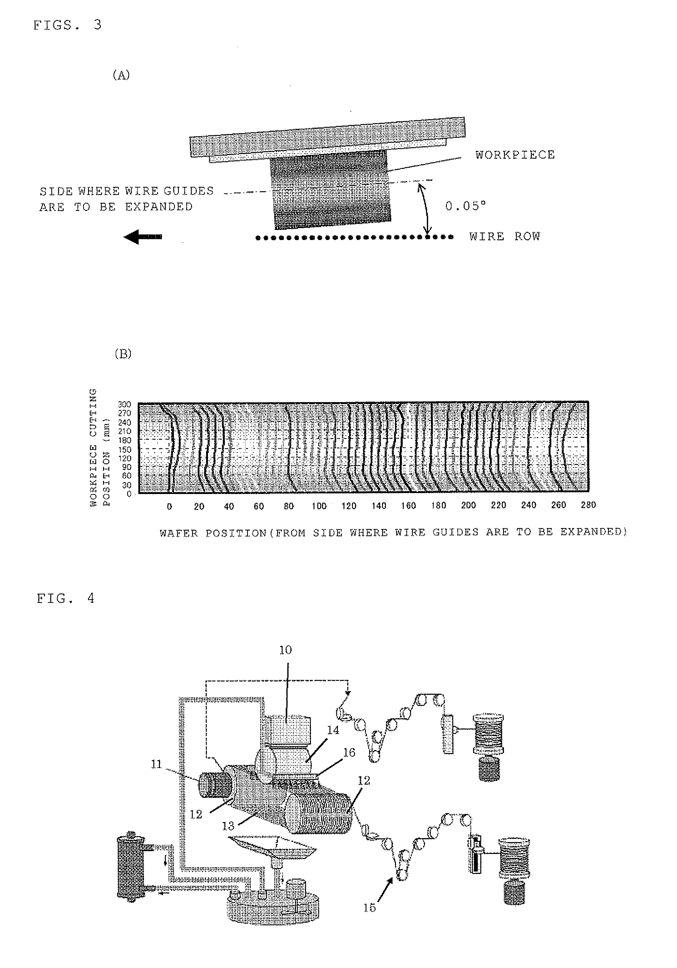
[0058]In view of this, in order to effectively offset the inflection of the slicing trajectory formed due to the expansion in an axial direction of the wire guides by the inflection of the slicing trajectory due to the skid of the wire, the workpiece was held in conditions where the workpiece axis was inclined by 0.1° in such a manner that the side far from the wire row plane was the side where the wire guides were to be axially expanded, as shown in FIG. 1(A). A silicon ingot having a diameter of 300 mm and an axial length of 300 mm was sliced in the same conditions as Example 1 except for the inclination angle. The inclination of the wor...


PUM

PropertyMeasurementUnit
inclination angleaaaaaaaaaa
axial lengthaaaaaaaaaa

Abstract

The present invention is a method for slicing a workpiece into wafers by pressing a cylindrical workpiece held with a workpiece holder against a wire row formed by a wire spirally wound between a plurality of wire guides and making the wire travel while supplying a slurry to a contact portion between the workpiece and the wire, wherein the workpiece is sliced with an axis direction of the workpiece inclined with respect to a plane formed by the wire row, after the workpiece is inclined in such a manner that a side far from the wire row plane is a side where the wire guides are to be axially expanded. As a result, there is provided a method for slicing that enable wafers having a good Warp shape to be obtained by precisely slicing a workpiece with a wire saw.

Description

TECHNICAL FIELD[0001]The present invention relates to a method for slicing a workpiece into wafers with a wire saw.BACKGROUND ART[0002]A wire saw is an apparatus in which a workpiece is pressed against a wire row spirally wound between a plurality of wire guides (grooved rollers), an abrasive fluid in a slurry state obtained by mixing free-abrasive grains into an oily or an aqueous coolant is supplied to a contact portion between the workpiece and a wire, and thereby the workpiece is sliced into many wafers by a grinding effect of the free-abrasive grains. Specifically, the free-abrasive grains in the supplied abrasive fluid are pushed into an inner portion of a wire groove (a slicing groove of the workpiece) by the wire to scrape a bottom portion of the groove of the workpiece while making the wire row travel in a reciprocating direction so that the workpiece is sliced.[0003]As described above, the workpiece is sliced into wafers by scraping the free-abrasive grains on the inner po...

Claims


Application Information

Patent Timeline
Patent Type & Authority Applications(United States)
IPC IPC(8): B28D5/00B24B1/00
CPCB24B27/0633B28D5/045B28D5/0088
Inventor KITAGAWA, KOJITOMII, KAZUYA
Owner SHIN-ETSU HANDOTAI CO LTD
Why Eureka
Try Eureka