

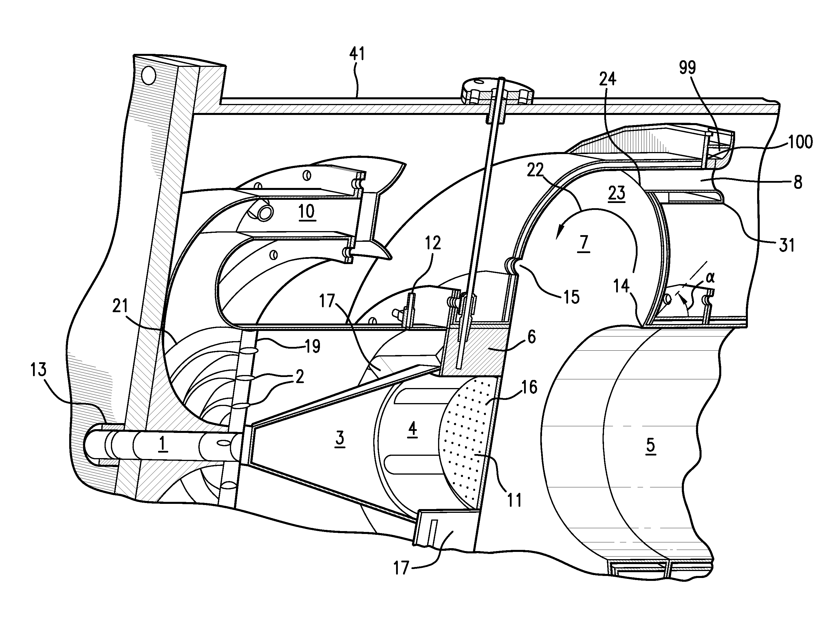
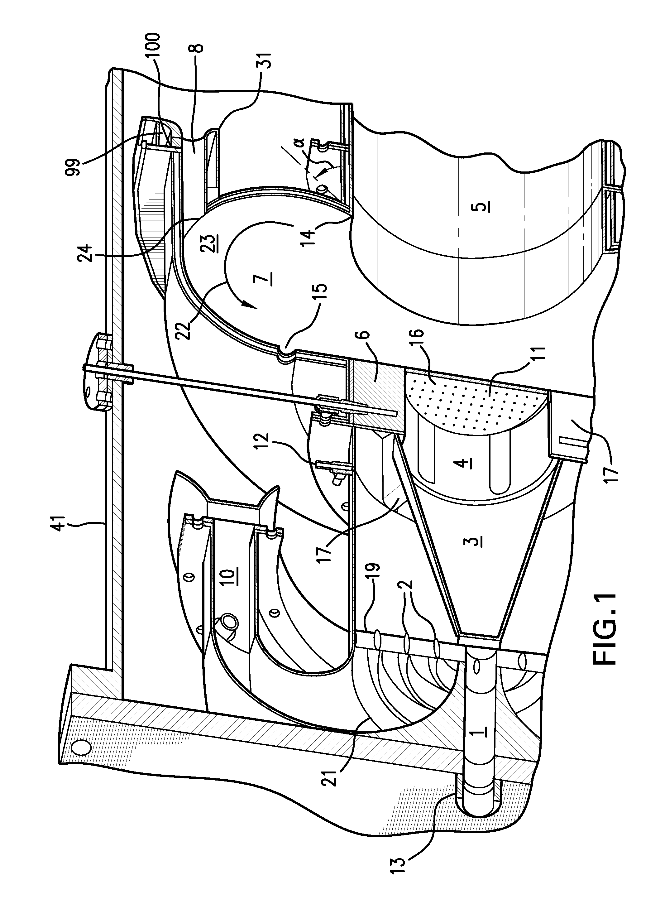
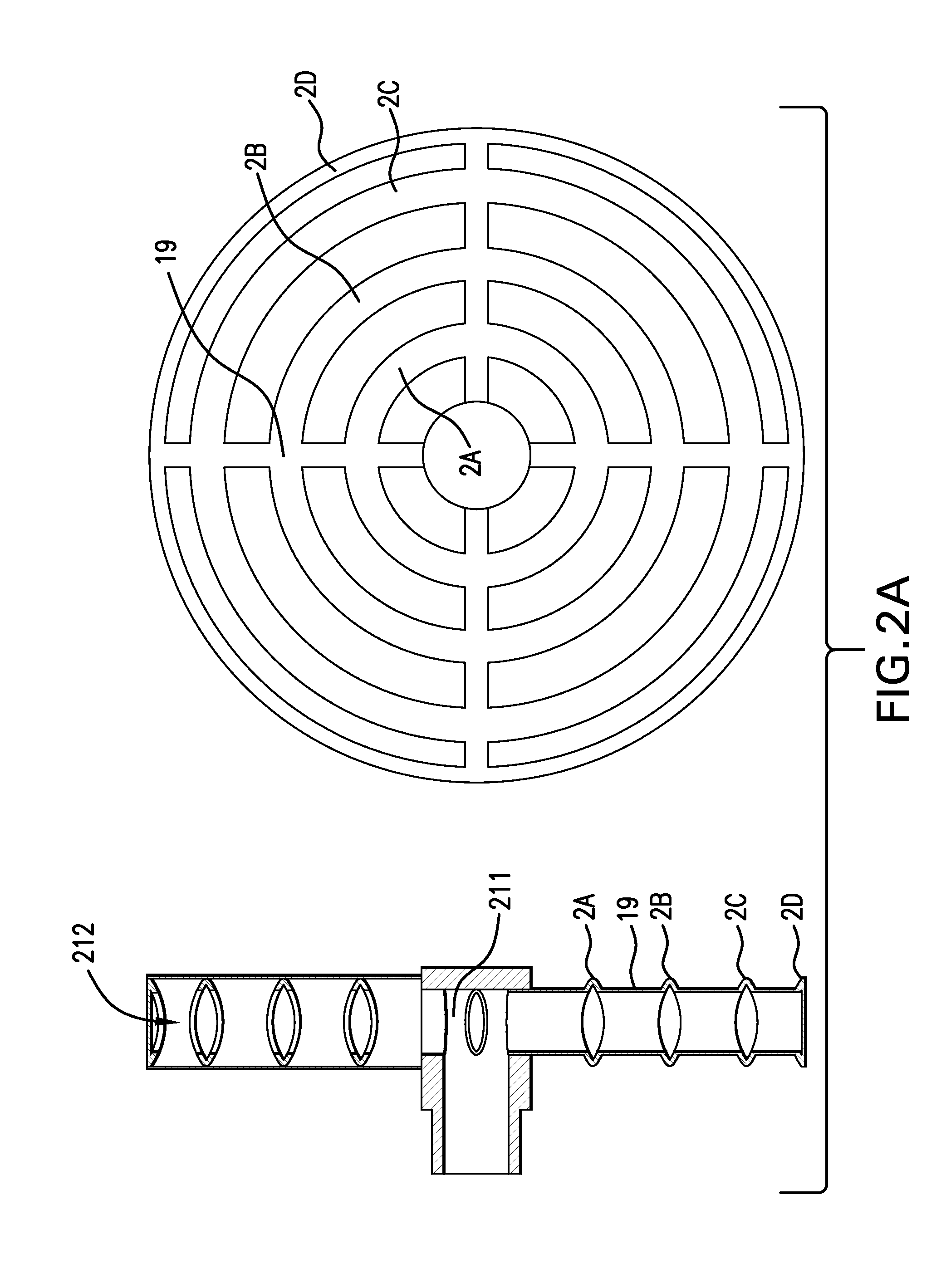
Inlet premixer for combustion apparatus
a combustion apparatus and premixer technology, applied in the field of combustion apparatuses, can solve the problems of adversely affecting emissions, not providing the most uniform fuel-air mixture, etc., and achieve the effect of superior fuel-air pre-mixing
- Summary
- Abstract
- Description
- Claims
- Application Information
AI Technical Summary
Benefits of technology
Problems solved by technology
Method used
Image

Examples
Embodiment Construction
[0039]The following is a detailed description of certain embodiments of the invention chosen to provide illustrative examples of how it may advantageously be implemented. The scope of the invention is not limited to the specific embodiments described, nor is it limited by any specific implementation, composition, embodiment or characterization depicted in the accompanying drawings or stated or described in the invention summary or the abstract. In addition, it should be noted that this disclosure describes a number of methods that each comprise a plurality of steps. Nothing contained in this written description should be understood to imply any necessary order of steps in such methods, other than as specified by express claim language.
[0040]The present disclosure is applicable to any gas turbine combustor or reaction chamber. Certain aspects of this disclosure are relevant to any energy release / conversion system having an inlet for gaseous or gas-borne liquid fuel and oxidant (air)....
PUM
 Abstract
Description
Claims
Application Information