Al technical title is built by PatSnap Al team. It summarizes the technical point description of the patent document.
a condensate pump and condensate technology, applied in the field of condensate pumps, can solve the problems of float to sink or malfunction, need for reliability over many years, and fouling
Active Publication Date: 2011-03-17
DIVERSITECH
View PDF61 Cites 64 Cited by
Summary
Abstract
Description
Claims
Application Information
AI Technical Summary
This helps you quickly interpret patents by identifying the three key elements:
Problems solved by technology
Method used
Benefits of technology
[0006]The present invention addresses the issues raised by the installation of a condensate pump in an extreme environment. Particularly, the condensate pump of the present inve
Problems solved by technology
Condensate pumps are often located in extreme environments and subjected to moisture, heat, and cold.
Moreover, condensate pumps are often installed in inaccessible locations where maintenance is difficult, and therefore reliability over many years is necessary.
The condensate pump float is in contact with the
Method used
Image
Click on the blue label to locate the original text in one second.
Reading with bidirectional positioning of images and text.
Examples
Embodiment Construction
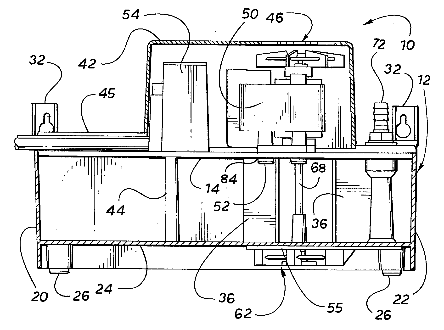
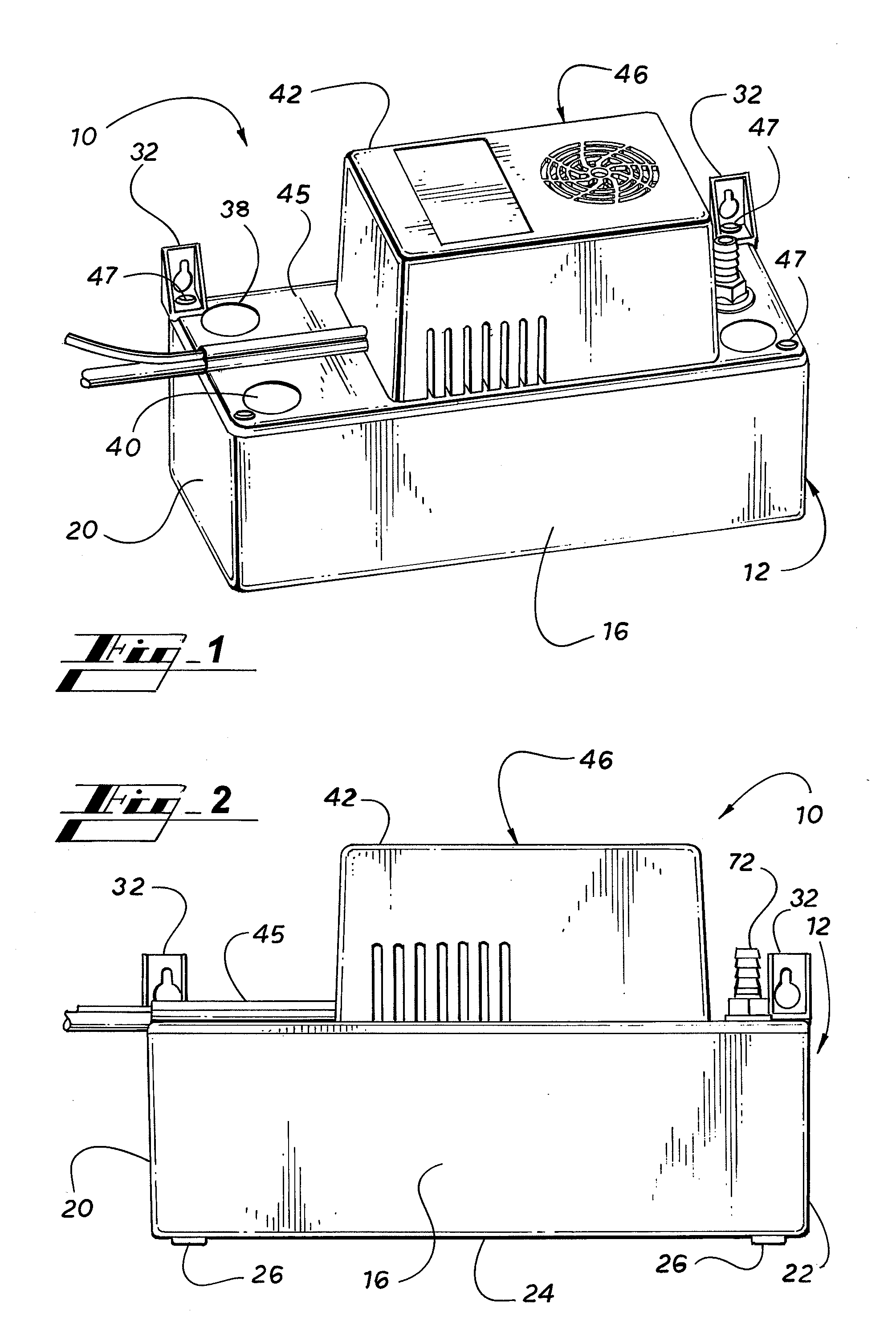
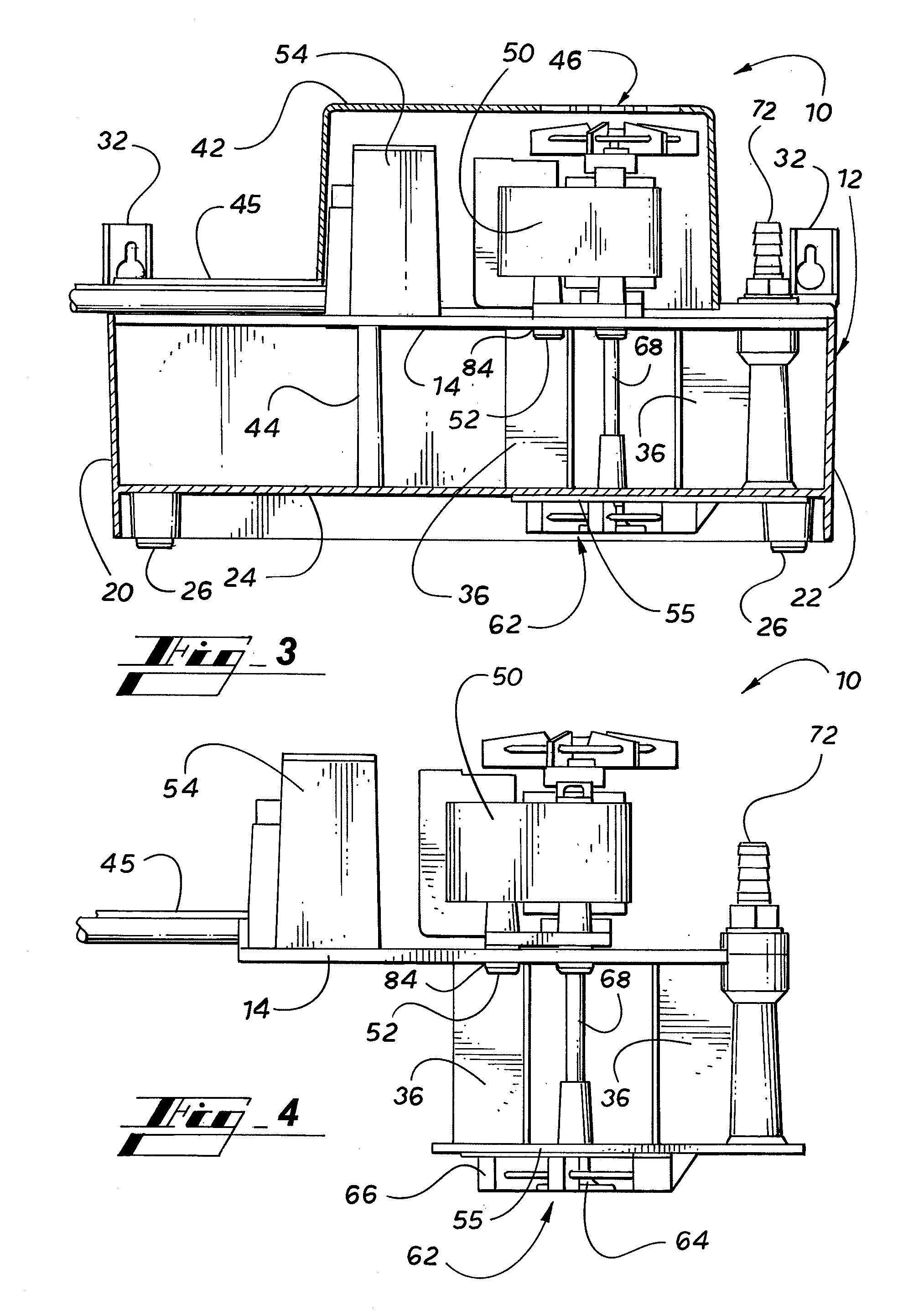
[0038]Turning to FIG. 1-7, a condensate pump 10 in accordance with the present invention comprises a reservoir 12, a top cover 46, and a support plate 14 (FIG. 4). The reservoir 12 comprises a water tight container with a front panel 16, a back panel 18, a left side panel 20, a right side panel 22, and a bottom panel 24. The reservoir may be of any geometric shape. The reservoir 12 has rubber support legs 26 located on the four corners of the bottom panel 24.
[0039]The top cover 46 comprises a cowl 42 and a flat base 45. The flat base 45 of the cover 46 is attached to the top of the reservoir 12 by means of cover screws 47. In addition, hanger brackets 32 are mounted to the reservoir 12 by means of the cover screws 47 adjacent the reservoir back panel 18. The hanger brackets 32 are used to mount the condensate pump 10 on a wall or other elevated support in order to make later access to the condensate pump 10 in some cases easier. The cowl 42 covers and protects a pump motor 50 and a ...
PUM
Abstract
A condensate pump for an HVAC system includes a reservoir for collecting condensate water, a pump motor connected to an impeller pump for pumping the condensate water out of the reservoir, and a floatless pump control module. The floatless pump's microcontroller detects the water level in the reservoir and, based on the water level in the reservoir, controls the operation of the pump motor, and if necessary, sounds an alarm and shuts down the HVAC system. The floatless pump microcontroller may employ an ultrasonic transducer or capacitance sensors to detect the level of condensate water in the reservoir. The microcontroller implements a variable water lift feature to pump the water using the lowest possible speed for the pump. The microcontroller implements a self-cleaning feature to pump stagnant water out of the reservoir and to pulse water in the drain line and the agitation of the water in the reservoir. The microcontroller implements an anti-clog feature to clear a clogged drain line when an overflow condition is detected.
Description
CLAIM OF PRIORITY[0001]This application is a continuation-in-part of copending U.S. patent application Ser. No. 11 / 277,445, filed Mar. 24, 2006, which claims priority from U.S. Provisional Patent Application Ser. No. 60 / 665,533, filed on Mar. 24, 2005, which is incorporated herein in its entirety, this application is a continuation-in-part of copending U.S. patent application Ser. No. 12 / 190,212, filed Aug. 12, 2008, which claims priority from U.S. Provisional Patent Application Ser. No. 60 / 956,741, filed on Aug. 20, 2007, which is incorporated herein in its entirety, and this application is a continuation-in-part of copending U.S. patent application Ser. No. 12 / 244,152, filed Oct. 2, 2008, which claims priority from U.S. Provisional Patent Application Ser. No. 60 / 976,962, filed on Oct. 2, 2007, which is incorporated herein in its entirety.FIELD OF THE INVENTION[0002]The invention relates to a condensate pump that collects condensate water from the evaporator of an HVAC system and p...
Claims
Application Information
Patent Timeline
Application Date:The date an application was filed.
Publication Date:The date a patent or application was officially published.
First Publication Date:The earliest publication date of a patent with the same application number.
Issue Date:Publication date of the patent grant document.
PCT Entry Date:The Entry date of PCT National Phase.
Estimated Expiry Date:The statutory expiry date of a patent right according to the Patent Law, and it is the longest term of protection that the patent right can achieve without the termination of the patent right due to other reasons(Term extension factor has been taken into account ).
Invalid Date:Actual expiry date is based on effective date or publication date of legal transaction data of invalid patent.