Diaphragm Pump

a diaphragm pump and pump body technology, applied in the direction of reciprocating piston engines, flexible wall reciprocating engines, positive displacement liquid engines, etc., can solve the problem that diaphragms having a size that may be useful for the desired delivery rate would be clearly more expensive, and achieve the effect of large stroke volume, large stroke volume and similar modulus of elasticity

Active Publication Date: 2011-03-17
FRAUNHOFER GESELLSCHAFT ZUR FOERDERUNG DER ANGEWANDTEN FORSCHUNG EV
View PDF5 Cites 19 Cited by
  • Summary
  • Abstract
  • Description
  • Claims
  • Application Information

AI Technical Summary

Benefits of technology

[0016]In embodiments of the invention, the pump diaphragm is formed of metal, for example stainless steel. This enables implementing pump diaphragms having a sufficient size and a sufficiently large stroke volume for the existing pressure requirements so as to enable the desired delivery rates. In this case, metal diaphragms are advantageous as compared to silicon diaphragms, since the cost of silicon diaphragms scales with the ...

Problems solved by technology

In this case, metal diaphragms are advantageous as compared to silicon diaphragms, since the cost of silicon diaphragms scales wi...

Method used


Image

  • Diaphragm Pump
  • Diaphragm Pump
  • Diaphragm Pump

Examples


Embodiment Construction

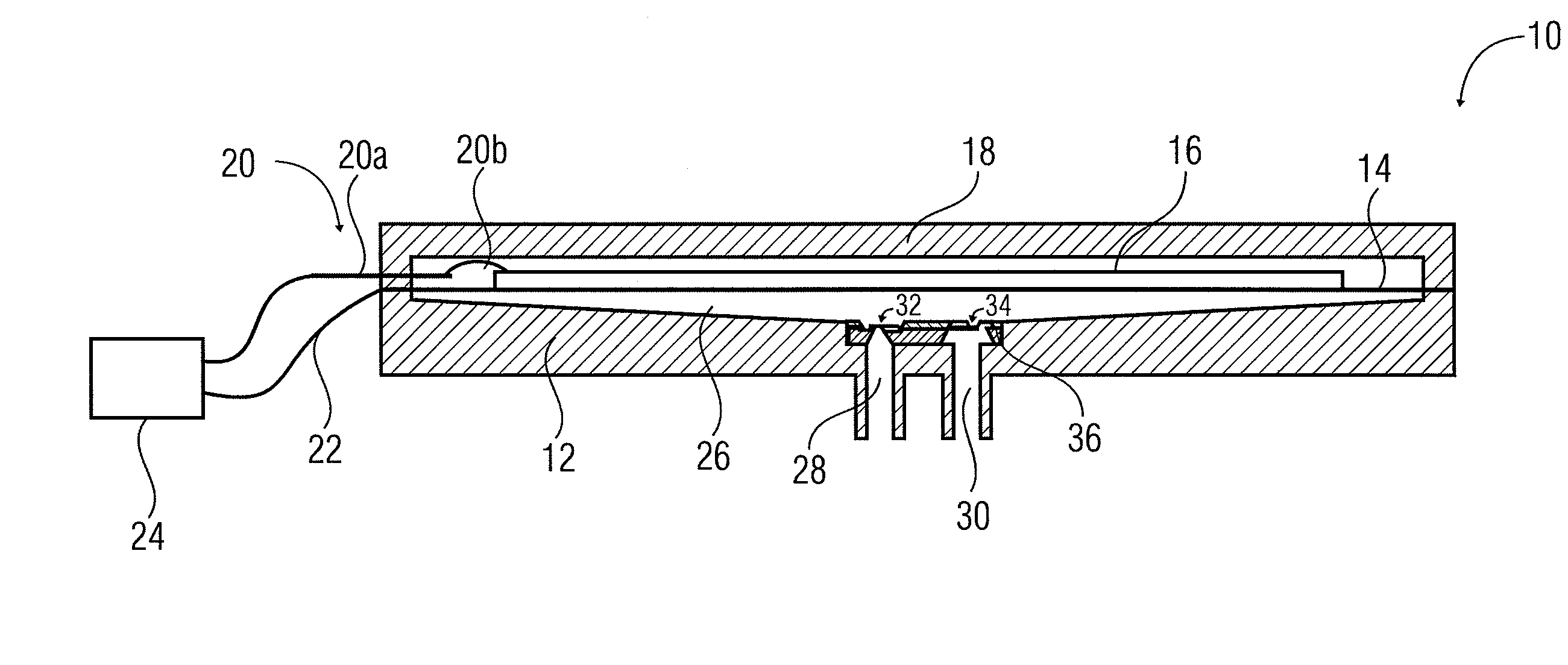
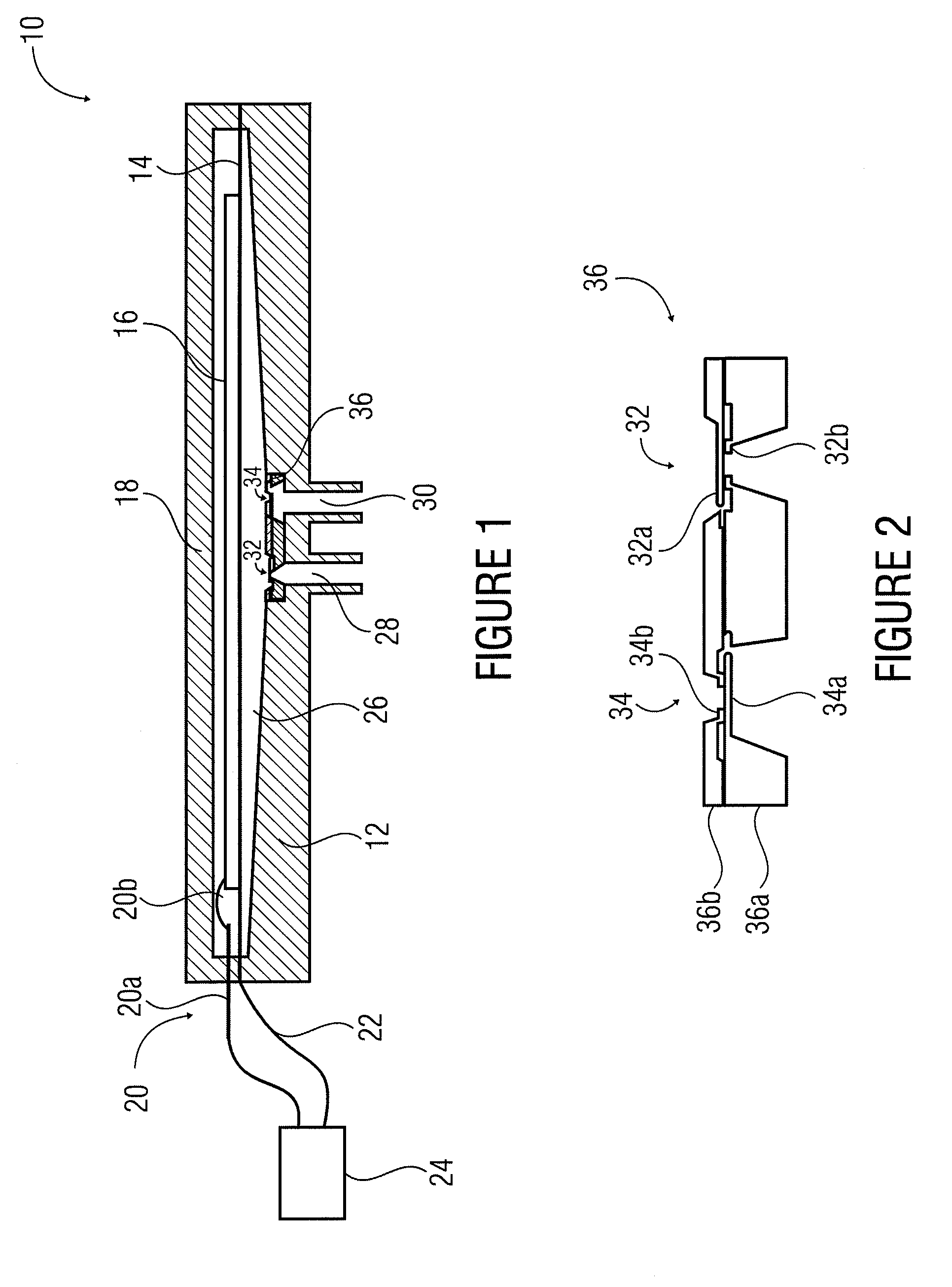
[0025]A schematic cross sectional view of an embodiment of an inventive diaphragm pump 10 is shown in FIG. 1. The diaphragm pump 10 comprises a pump body 12, a pump diaphragm 14, a piezo actuator 16 arranged on the pump diaphragm 14, and a cover 18. In embodiments, the piezo actuator 16 and the pump diaphragm 14 form a piezo bending converter. A driver means 24 is provided for applying, via electric connections 20 and 22, the voltages that may be useful for actuating the piezo actuator. In embodiments of the invention, the pump diaphragm 14 is a metallic pump diaphragm, so that the electric connection 22 may apply a first potential to the piezo actuator 16 via the pump diaphragm 14. In embodiments, the second potential is applied to the opposite side of the piezo actuator via the electric connection 20 which may comprise, for example, a metal platelet 20a and a bonding wire 20b.

[0026]The pump body 12 comprises a recess which together with the pump diaphragm 14 defines a pump chambe...


PUM


Abstract

A diaphragm pump includes a pump chamber having an inlet opening and an outlet opening. A passive silicon check valve is provided at the inlet opening, and a passive silicon check valve is provided at the outlet opening. The diaphragm pump further includes a metallic pump diaphragm that adjoins the pump chamber.

Description

CROSS-REFERENCE TO RELATED APPLICATION[0001]This application is a U.S. National Phase entry of PCT / EP2007 / 009144 filed Oct. 22, 2007 which is incorporated herein by references hereto.BACKGROUND OF THE INVENTION[0002]The present invention relates to diaphragm pumps.[0003]Micro pumps taking up little installation space have been known from conventional technology. For example, from DE 197 19 862 A1, a micro diaphragm pump comprising passive check valves has been known which comprises a pump diaphragm that is movable into first and second positions by means of driving means. A pump body is connected to the pump diaphragm to define a pump chamber between them. An inlet opening and an outlet opening are each provided with passive check valves. In addition to a piezoelectric drive for the pump diaphragm, an electrostatic drive has also been described. The pump diaphragm and check valves are structured in respective silicon substrates. In addition, starting materials mentioned for the pump...

Claims


Application Information

Patent Timeline
IPC IPC(8): F01B19/00
CPCF04B45/047F04B43/046
Inventor WACKERLE, MARTINRICHTER, MARTIN
Owner FRAUNHOFER GESELLSCHAFT ZUR FOERDERUNG DER ANGEWANDTEN FORSCHUNG EV
Why Eureka
Try Eureka