Electrolytic copper plating bath and method for electroplating using the electrolytic copper plating bath

a technology of electrolysis and copper plating, applied in the direction of printed circuits, electrical equipment, printed circuit manufacturing, etc., can solve the problems of corner cracks, the plating bath of the related technique may not be usable for through hole plating, and the thickness of film at the inner bottom of the blind via hole becomes thin

Active Publication Date: 2011-03-17
C UYEMURA & CO LTD
View PDF4 Cites 24 Cited by
  • Summary
  • Abstract
  • Description
  • Claims
  • Application Information

AI Technical Summary

Benefits of technology

[0016]With the electrolytic copper plating bath, and the electroplating method that uses the electrolytic copper plating bath, according to the embodiment of the present invention, it is possible to effect plati...

Problems solved by technology

However, in case the plating bath of the related technique, aimed at via-filling, is used for through hole plating, the film thickness at the through hole corner becomes unusually thin, thus possibly causing the corner crack.
The plating bath of the related technique may thus not be usable for through hole...

Method used


Image

  • Electrolytic copper plating bath and method for electroplating using the electrolytic copper plating bath
  • Electrolytic copper plating bath and method for electroplating using the electrolytic copper plating bath
  • Electrolytic copper plating bath and method for electroplating using the electrolytic copper plating bath

Examples


examples

[0063]Concrete Examples of the present invention will now be described. It is noted that these Examples are not to be interpreted as limiting the scope of the present invention.

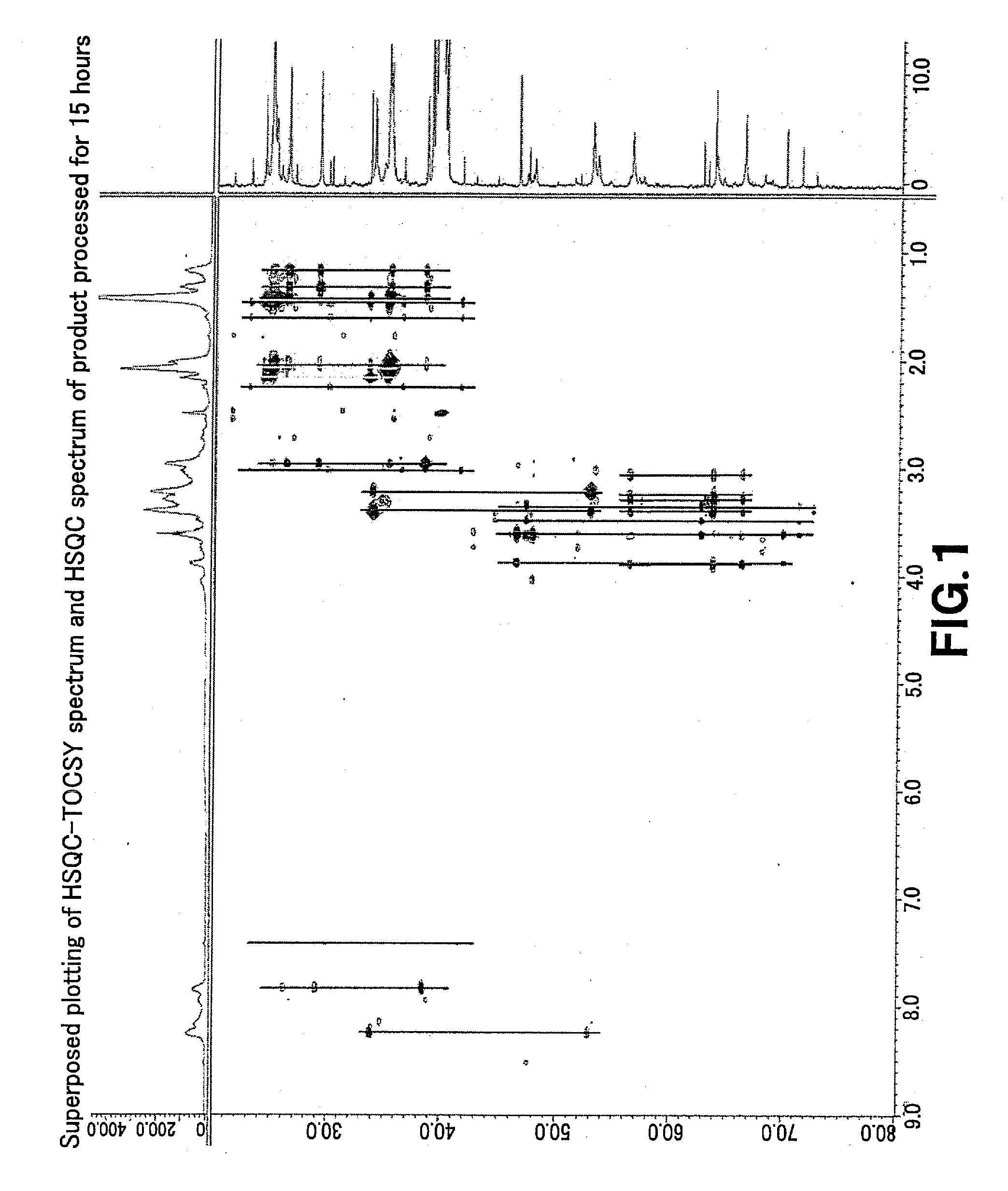
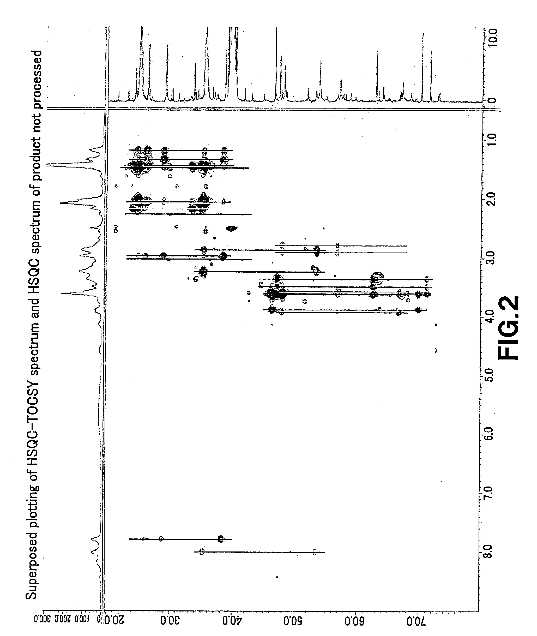
[0064]The structures of the epichlorohydrin modified product and the compound obtained on processing by heating it were analyzed as will be explained in detail below. Initially, the epichlorohydrin modified product was synthesized as follows:

[0065]9.7 g of water were charged at ambient temperature (20 to 30° C.) into a vessel. 58 g of ε-caprolactam were charged therein under stirring, and the reaction system was heated to 30 to 35° C. 37.8 g of adipic acid were added to the resulting solution under agitation. The resulting reaction system was heated to approximately 115 to 122° C. under refluxing and kept for two hours. The bath temperature was then cooled to approximately 100° C. (100 to 110° C.). As the temperature was kept, 52.9 g of diethylene triamine were added to the reaction system within one hour. By...


PUM

PropertyMeasurementUnit
Volumeaaaaaaaaaa
Temperatureaaaaaaaaaa

Abstract

For use for a circuit board where a through hole and a blind via hole co-exist, an electrolytic copper plating bath in which the covering power for the through hole and the plugging performance for the blind via hole are sufficient, and an electroplating method that uses the electrolytic copper plating bath, are disclosed. The electrolytic copper plating bath is mainly composed of a water-soluble copper salt, sulfuric acid and chloride ions. A polyamide polyamine, obtained on processing by heating of an epichlorohydrin modified product of a polycondensation product of diethylene triamine, adipic acid and ε-caprolactam, is contained in the bath as a leveler.

Description

BACKGROUND OF THE INVENTION[0001]1. Field of the Invention[0002]This invention relates to an electrolytic copper plating bath and to an electroplating method that uses it. More particularly, it relates to the electrolytic copper plating bath that may be applied with advantage to a circuit board where blind via holes and through holes exist together, and the method for electroplating using the electrolytic copper plating bath.[0003]2. Description of Related Art[0004]As the electronic components are becoming smaller in size, an increasing demand has been raised towards elevating their integration degree. To meet such demand, the packaging method is transitioning from peripheral terminal or area terminal packaging towards three-dimensional packaging. For this reason, attempts are being made to provide for current conduction to or connection of a semiconductor chip or an interposer by a through-electrode. As in the copper damocene process or in via filling for a printed circuit board, a...

Claims


Application Information

Patent Timeline
IPC IPC(8): C25D5/02C25D3/38
CPCC25D5/02C25D3/38C25D7/00
Inventor ISONO, TOSHIHISAOMURA, NAOYUKISHIMIZU, KOJITACHIBANA, SHINJI
Owner C UYEMURA & CO LTD
Why Eureka
Try Eureka