Communication apparatus, communication system, wire harness and communication method

a communication system and wire harness technology, applied in the field of communication systems, can solve problems such as digital errors, and achieve the effects of reducing weight, efficient and stable communication, and efficient and stable high-speed communication

Inactive Publication Date: 2011-03-17
AUTONETWORKS TECH LTD +2
View PDF11 Cites 31 Cited by
  • Summary
  • Abstract
  • Description
  • Claims
  • Application Information

AI Technical Summary

Benefits of technology

[0066]In an aspect according to the present invention, each communication apparatus is mounted on a vehicle. As the communication system mounted on the vehicle is especially required for the weight reduction, the communication through the electric power line can reduce the weight. As the communication system mounted on the vehicle is additionally required for the stable, the efficient and the fast transmission without errors since transmitting information about the cruise control of the vehicle, it is possible to implement the efficient and the stable communication with utilizing two of different frequencies.
[0067]In an aspect according to the present invention, each communication apparatus performs transmitting information through the electric power line with any one of two frequencies which have different frequencies from each other lower than the dip frequency estimated in accordance with the physical condition and the circuit structure of electric power line. Therefore, the communication through the electric power line can save the required lines, avoid the dip frequency and implement the efficient and the stable high-speed communication.
[0068]In an aspect according to the present invention, it is configured to change the output/non-output of the carrier wave based on the digital value of sent data for modulating the sending data, to superimpose the modulated signal on the electric power line for outputting, and to arbitrate in accordance with the existence of change in the output signal. Therefore, the communication apparatus can perform the high-speed data transmission thr

Problems solved by technology

When the communication utilizes the frequency band within which t

Method used


Image

  • Communication apparatus, communication system, wire harness and communication method
  • Communication apparatus, communication system, wire harness and communication method
  • Communication apparatus, communication system, wire harness and communication method

Examples


embodiment 1

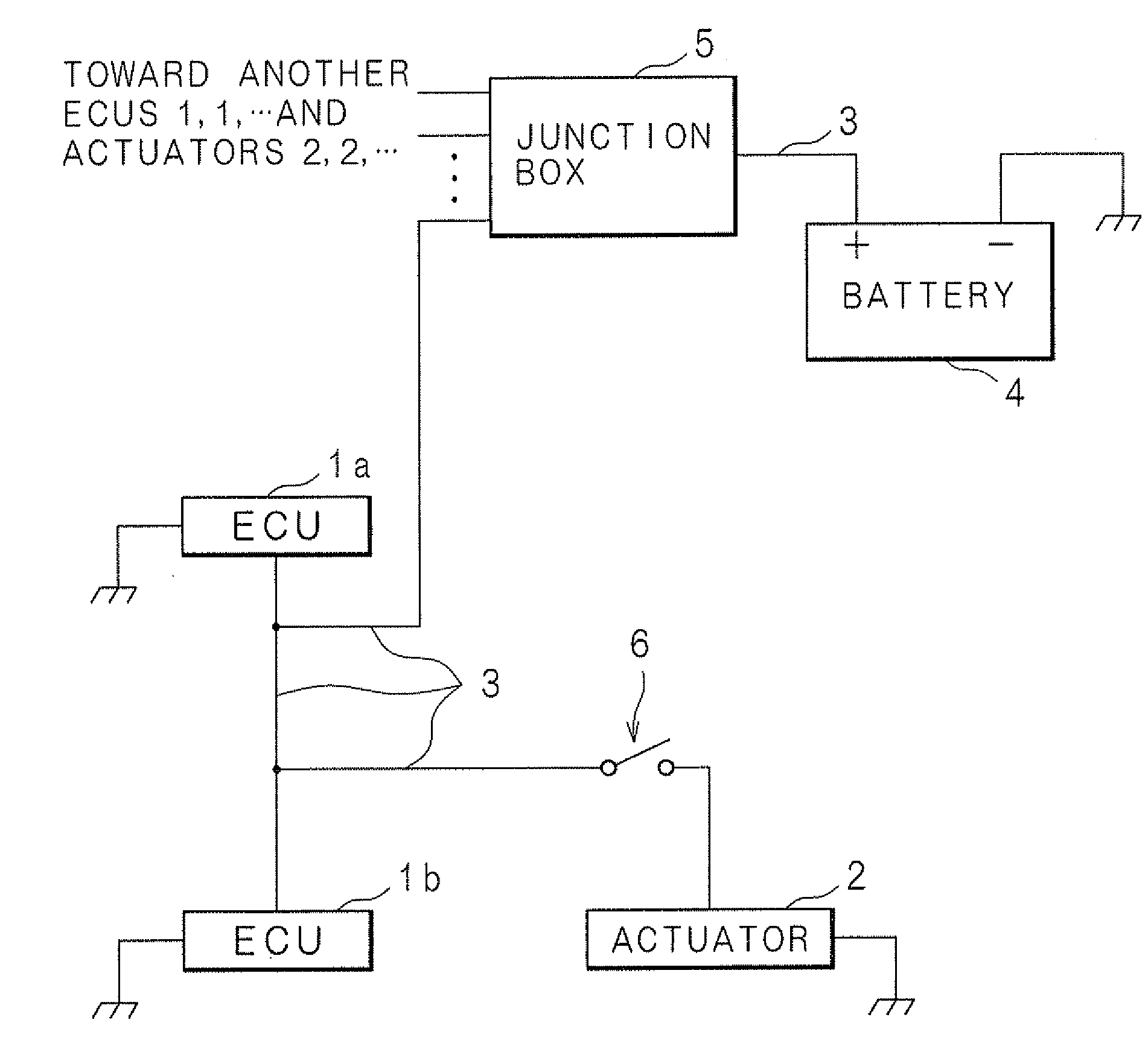
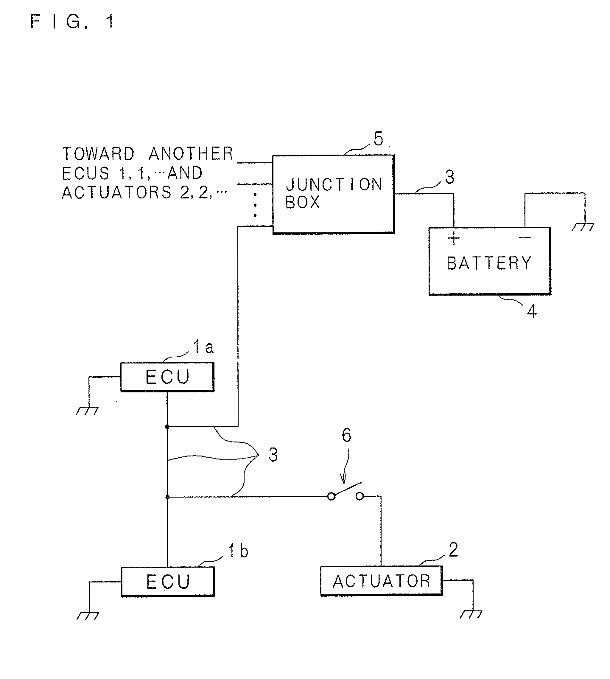
[0094]FIG. 1 is a block diagram showing a configuration of a communication system according to an embodiment 1. The communication system is configured to include: plural ECUs 1, 1, . . . ; actuators 2, 2, . . . that work on the basis of control data sent from the ECUs 1, 1, . . . ; electric power lines 3, 3, . . . for supplying electric power to respective ECUs 1, 1, . . . and actuators 2, 2, . . . ; a battery 4 that supplies electric power through the electric power lines 3, 3, . . . to respective apparatuses; branch points of the electric power lines 3, 3, . . . and a junction box 4 for relaying.

[0095]The electric power is stored in the battery 4 by an alternator (not shown) that generates electric power with utilizing power obtained from an engine. The battery 4 has a terminal (minus terminal) that is grounded and the other terminal (plus terminal) that is connected to the junction box 5 through the electric power line 3. For example, the battery 4 supplies 12V driving voltage to...

embodiment 2

[0132]In an Embodiment 2, it is Configured to Transmit Data between the ECUs 1, 1, . . . , and to utilize a format for transmitting the data different from the format utilized in the embodiment 1. The configurations of communication system according to the embodiment 2 are similar to those according to the embodiment 1, thus are provided with similar numerals and are not described in detail. It will be described below about the format of data transmitted by the communicating unit 12.

[0133]FIG. 6A and FIG. 6B are explanation views showing formats of data transmitted between the ECUs 1, 1, . . . according to the embodiment 2. FIG. 6A shows example contents of attribute data, and FIG. 6B shows example contents of data. In both FIG. 6A and FIG. 6B, the left side in the figure represents the beginning of data.

[0134]As shown in FIG. 6A, the attribute data includes: ID for identifying data contents; data length; information representing the necessity of re-sending data; and type of parity....

embodiment 3

[0145]In an Embodiment 3, the Data to be Transmitted is Configured to conform to the CAN, and the communication is implemented by the conventional CAN communication function (CAN controller) included in each ECU. Furthermore, the embodiment 3 utilizes the ASK as the modulation method for the carrier waves utilized by the first transmitting circuit 15 and the second transmitting circuit 16, although the modulation method is not limited to any method in the embodiments 1 and 2. In addition, although the embodiments 1 and 2 are configured to select one frequency among the two different frequencies f1 and f2 of carrier waves for sending data, the embodiment 3 is configured to utilize 12 MHz carrier wave among the preferable band range 2-20 MHz for sending data, instead of selecting one frequency among the two different frequencies f1 and f2 of carrier waves. Alternatively, the embodiment 3 described below may be configured to select one frequency among two carrier waves having different...


PUM


Abstract

Plural ECUs are connected to each other by an electric power line that is for supplying electric power. Each ECU sends information with a carrier wave having a first frequency lower than a dip frequency estimated by the physical condition and the circuit structure of electric power line, or having a second frequency lower than the first frequency. Or, the physical condition and the circuit structure of electric power line are determined, on the contrary, to make the dip frequency become higher than the frequency of utilized carrier wave. The frequency utilized for sending information may be selected in accordance with the contents of information.

Description

[0001]This application is the national phase under 35 U.S.C. §371 of PCT International Application No. PCT / JP2009 / 058709 which has an International filing date of May 8, 2009 and designated the United States of America.BACKGROUND OF THE INVENTION[0002]1. Field of the Invention[0003]The present invention relates to a communication system for making a plurality of communication apparatus send and receive information through electric power line. Furthermore, the present invention relates to a communication apparatus, a communication system, a wire harness and a communication method for implementing stable high-speed communication.[0004]2. Description of Related Art[0005]It is recently known in several fields to utilize a system having many communication apparatuses, in which each communication apparatus is provided with a certain function and connected with other communication apparatuses in order to perform many operations through the data exchange between many communication apparatus...

Claims


Application Information

Patent Timeline
IPC IPC(8): H04B1/38H02G3/04H04B3/54H04Q9/00
CPCH04B3/544H04B2203/5458H04B2203/5412
Inventor ISHIKO, SHINICHI
Owner AUTONETWORKS TECH LTD
Why Eureka
Try Eureka