Polymeric Stent and Method of Making Same

Inactive Publication Date: 2011-03-17
ABBOTT CARDIOVASCULAR
View PDF70 Cites 117 Cited by
  • Summary
  • Abstract
  • Description
  • Claims
  • Application Information

AI Technical Summary

Benefits of technology

[0014]A method for making a stent, according to aspects of the present invention, comprises deforming a precursor tube of a polymer formulation to form a deformed tube. The deforming includes maintaining fluid pressure in the tube at a process pressure from about 50 psi to about 200 psi, heating the tube to a process temperature from about 100 deg. F. to about 300 deg F., radially expanding the precursor tube according to a radial expansion ratio between about 100% and about 600% during the maintaining of fluid pressure and the heating, and a

Problems solved by technology

Relatively low radial strength potentially contributes to relatively high recoil of polymer stents after implantation into an anatomical lumen.
Furthermore, another potential problem with polymer stents is that struts can crack or fracture during crimping, delivery and deployment, especially for brittle polymers.
Physio

Method used


Image

  • Polymeric Stent and Method of Making Same
  • Polymeric Stent and Method of Making Same
  • Polymeric Stent and Method of Making Same

Examples


Embodiment Construction

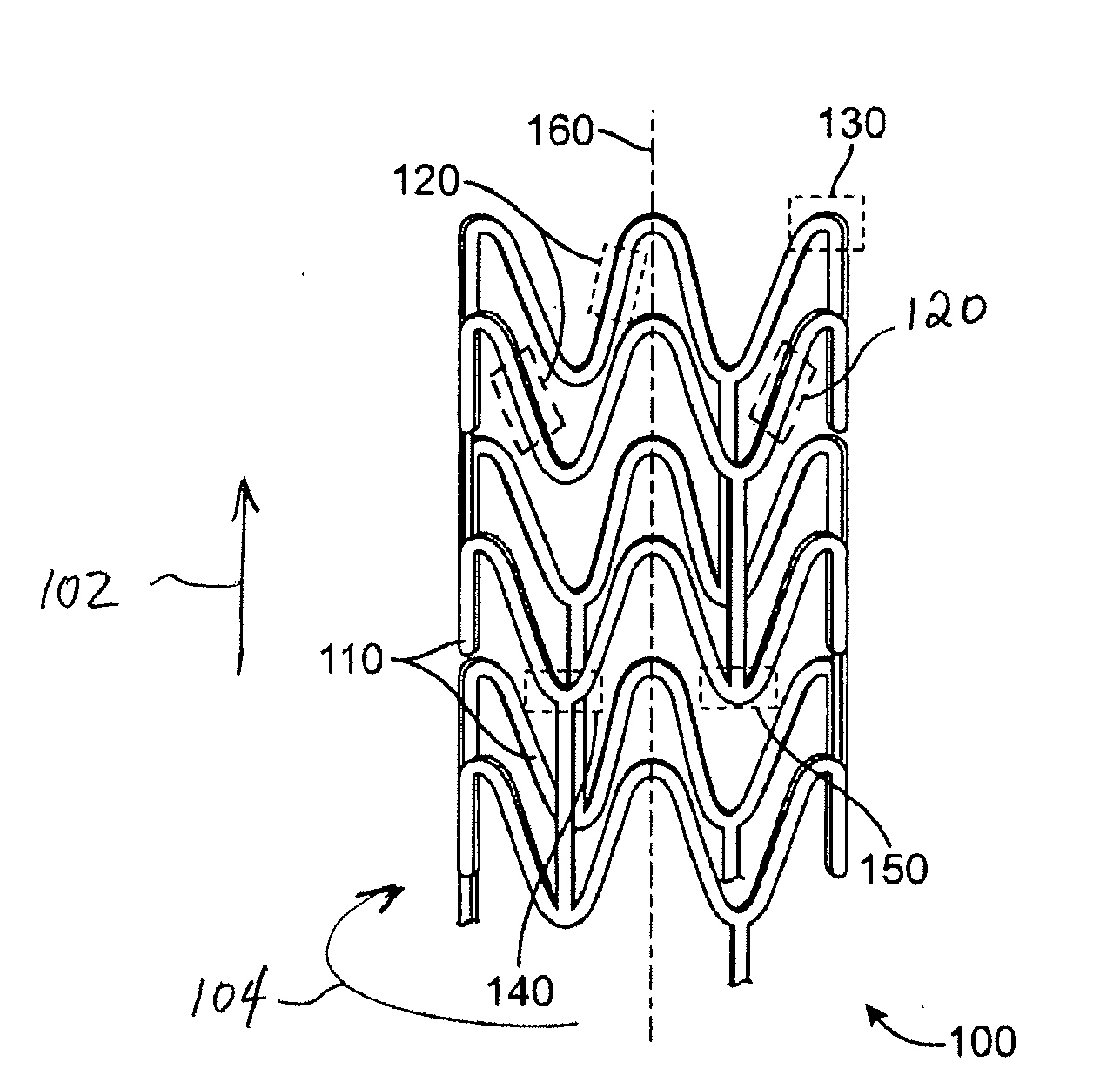
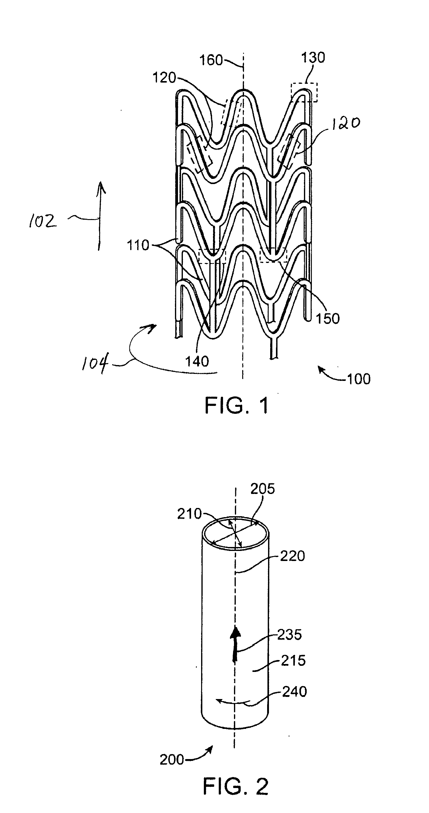
[0026]The various embodiments of the present invention relate to methods of fabricating a polymeric stent that has good or optimal toughness and selected mechanical properties along the axial, radial and circumferential directions. The present invention can be applied to devices including, but is not limited to, self-expandable stents, balloon-expandable stents, stent-grafts, grafts (e.g., aortic grafts), and generally to tubular implantable medical devices.

[0027]For the purposes of the present invention, the following terms and definitions apply:

[0028]The glass transition temperature (referred to herein as “Tg”) is the temperature at which the amorphous domains of a polymer change from a brittle vitreous state to a solid deformable or ductile state at atmospheric pressure. In other words, Tg corresponds to the temperature where the onset of segmental motion in the chains of the polymer occurs. Tg of a given polymer can be dependent on the heating rate and can be influenced by the t...


PUM

PropertyMeasurementUnit
Fractionaaaaaaaaaa
Fractionaaaaaaaaaa
Fractionaaaaaaaaaa

Abstract

A stent may be formed from a PLLA tubular polymer construct that is deformed in a blow mold. A desirable polymer morphology resulting in improved stent performance is obtained with a selected radial axial expansion ratio from about 20% to about 70%, a selected radial expansion ratio from about 400% to about 500%, a selected axial rate of deformation propagation at or about 0.3 mm/minute, a selected expansion pressure at or about 130 psi, and a selected expansion temperature that does not exceed 200 deg F. The tubular polymer construct may also be made of PLGA, PLLA-co-PDLA, PLLD/PDLA stereocomplex, and PLLA-based polyester block copolymer containing a rigid segment of PLLA or PLGA and a soft segment of PCL or PTMC.

Description

FIELD OF THE INVENTION[0001]This invention relates generally to fabrication of implantable prostheses, more particularly, to fabrication of stents from blow molded polymeric tubes.BACKGROUND OF THE INVENTION[0002]Radially expandable endoprostheses are artificial devices adapted to be implanted in an anatomical lumen. An “anatomical lumen” refers to a cavity, duct, of a tubular organ such as a blood vessel, urinary tract, and bile duct. Stents are examples of endoprostheses that are generally cylindrical in shape and function to hold open and sometimes expand a segment of an anatomical lumen. Stents are often used in the treatment of atherosclerotic stenosis in blood vessels. “Stenosis” refers to a narrowing or constriction of the diameter of a bodily passage or orifice. In such treatments, stents reinforce the walls of the blood vessel and prevent restenosis following angioplasty in the vascular system. “Restenosis” refers to the reoccurrence of stenosis in a blood vessel or heart v...

Claims


Application Information

Patent Timeline
IPC IPC(8): A61F2/06B29C49/08
CPCA61F2/91A61F2240/001B29L2031/7542B29C2049/0089B29C49/00B29C2949/08B29C2049/7831B29C2049/7862
Inventor WANG, YUNBINGGADA, MANISH B.
Owner ABBOTT CARDIOVASCULAR
Why Eureka
Try Eureka