Electric door lock

a door lock and electric technology, applied in the field of door locks, can solve the problems of high manufacturing cost and inconvenience of mechanical door locks operated by keys, and achieve the effects of low manufacturing cost, convenient manufacturing, and simple construction

Active Publication Date: 2011-03-24
TONG LUNG METAL IND
View PDF2 Cites 36 Cited by
  • Summary
  • Abstract
  • Description
  • Claims
  • Application Information

AI Technical Summary

Benefits of technology

[0006]An object of the present invention is to provide an electric door lock which can be operated either manually o

Problems solved by technology

A mechanical door lock operated by a key is sometimes inconvenient because the user may not have the key in hand.
Although an electric door lock operated el

Method used


Image

  • Electric door lock
  • Electric door lock
  • Electric door lock

Examples


Embodiment Construction

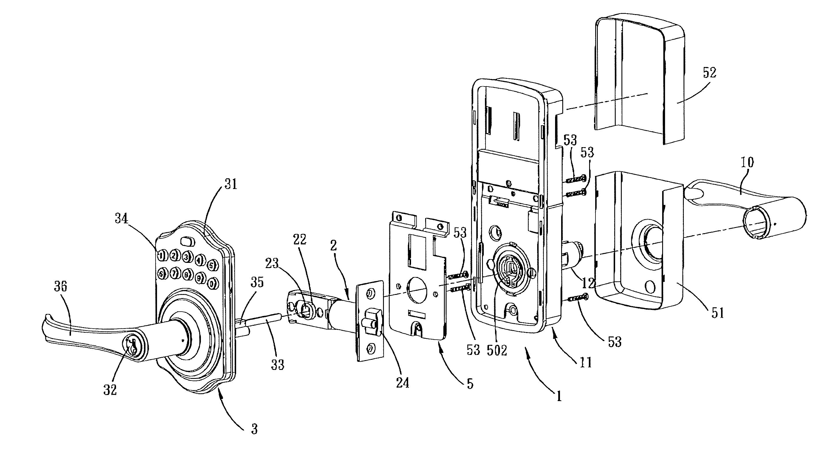
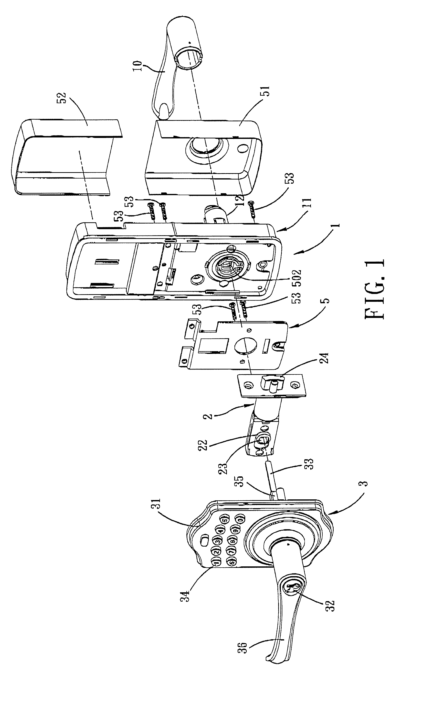
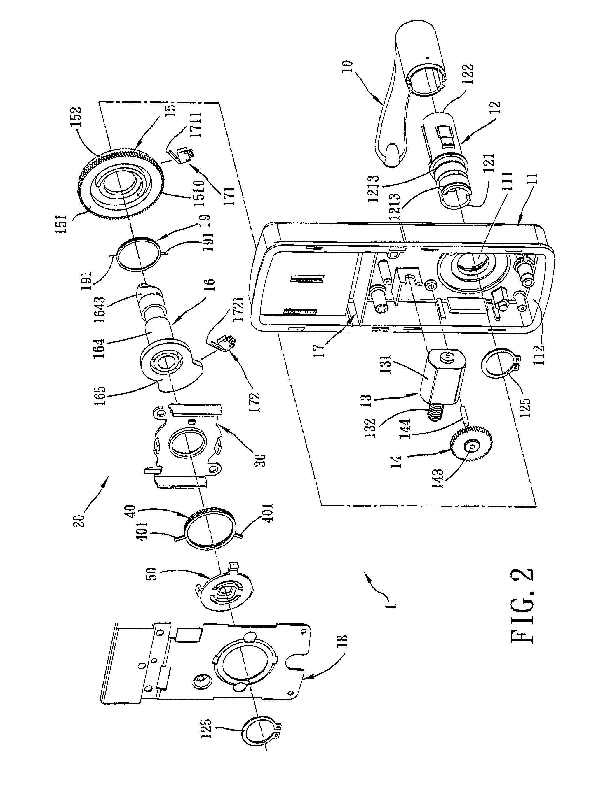
[0031]Referring to FIGS. 1 and 2, the preferred embodiment of an electric door lock according to the present invention is shown to comprise a housing 11, an inner drive tube 12, a drive unit 13, a transmission wheel 15, a torsion spring 19, a driven wheel unit 16, an electronic control unit 17, a torque restoring mechanism 20, and a frame 18.

[0032]The housing 11 has a through hole 111 and a receiving space 112.

[0033]Referring to FIGS. 2 and 8, the inner drive tube 12 defines an axially extending hole 124, and has first and second ends 121,122, an annular flange 123 therebetween, two axial slots 1211 opening at the first end 121 and extending axially towards the second end 122, and two arc-shaped slots 1212 extending circumferentially near the first end 121 and communicated with the axial slots 1211, respectively. In addition, two spaced apart annular grooves 1213 are formed in an outer surrounding surface near the first end 121. The first end 121 extends through the through hole 111...


PUM


Abstract

An electric door lock includes a transmission wheel driven by a motor and incorporating a spring with a driving end to drive a driven wheel. The transmission wheel and the driven wheel are rotatably sleeved around an inner drive tube connected to an inner handle. A spindle is inserted into the inner drive tube and has an operating end exposed from the inner handle. The driven wheel is connected integrally to the spindle for rotation. Preferably, a coupling piece extends through an arc-shaped slot in the inner drive tube and interconnects the driven wheel and the spindle.

Description

CROSS-REFERENCE TO RELATED APPLICATION[0001]This application claims priority of Taiwanese Utility Model Application No. 098217614, filed on Sep. 24, 2009, the disclosure of which is herein incorporated by reference.BACKGROUND OF THE INVENTION[0002]1. Field of the Invention[0003]This invention relates to a door lock, more particularly to an electric door lock which functions both manually and electrically.[0004]2. Description of the Related Art[0005]Generally, the designs of door locks are directed towards simplicity, convenience, as well as enhancement for security. A mechanical door lock operated by a key is sometimes inconvenient because the user may not have the key in hand. Although an electric door lock operated electrically is relatively convenient, the electric system and transmission mechanism are complicated in structure, which causes a higher manufacturing cost.SUMMARY OF THE INVENTION[0006]An object of the present invention is to provide an electric door lock which can be...

Claims


Application Information

Patent Timeline
IPC IPC(8): E05B47/02E05B47/06
CPCE05B17/22E05B47/0012E05B47/0661E05B55/005E05B2047/0084E05B2047/0031E05B2047/0054E05B2047/0067E05B2047/002Y10T70/5832Y10T70/7068Y10T70/7102Y10T70/7107Y10T70/7113Y10T70/7136Y10T70/8027Y10T292/307Y10T292/82
Inventor CHIOU, MING-SHYANGSUN, CHIA-MINHUANG, YU-TINGLIN, YU-LE
Owner TONG LUNG METAL IND
Why Eureka
Try Eureka