Wear resistant clutch plate

a technology of clutch plate and wear resistance, applied in the direction of friction clutch, mechanical actuated clutch, clutch, etc., can solve the problems of splined engagement of teeth and channels, lateral wear and tear of splined engagements, and excessive wear of teeth themselves, so as to reduce or eliminate engagement wear

Inactive Publication Date: 2011-03-24
TRI COMPONENT PROD
View PDF16 Cites 25 Cited by
  • Summary
  • Abstract
  • Description
  • Claims
  • Application Information

AI Technical Summary

Benefits of technology

[0008]It is accordingly an object of the present invention to provide a structural modification of a gear tooth-channeled splined engagement configuration and to provide a method of reducing or eliminating engagement wear.
[0009]It is a further object of the present invention to provide the modification in a clutch plate structure without other operational dimensional changes such as reduced number of engaging teeth.

Problems solved by technology

Despite such advantages, splined engagements of teeth and channels are subject to lateral wear and tear in the direction of limited axial teeth travel within the channels.
Vehicular clutch drive plates and particularly those used in automotive transmissions and torque converters exemplify gear teeth splined engagements subject to such detrimental wear.
After numerous engagements and disengagements during use, the relatively sharp external teeth of the drive plate may cut fretting wear into the engaging surfaces of the front cover.
In addition, the teeth themselves often also exhibit excessive wear.
The result of the undue wear is erratic clutch engagement and undesirable noise.
In addition, excessively fretted parts must be replaced at considerable expense.
However, these lateral extensions introduce detrimental structural problems of increased tooth spacing and reduced number of engaging teeth in the design of the clutch plates (GB 1522825).
The structures disclosed therein cannot bridge existing or potential wear points due to limited material available for tooth edge modification.

Method used


Image

  • Wear resistant clutch plate
  • Wear resistant clutch plate
  • Wear resistant clutch plate

Examples


Embodiment Construction

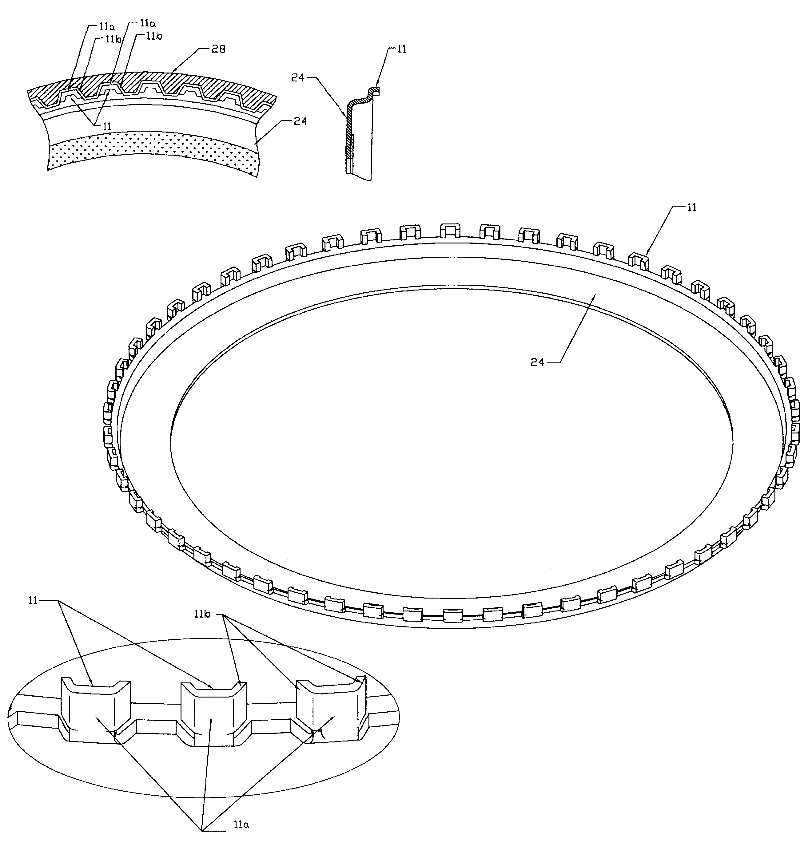
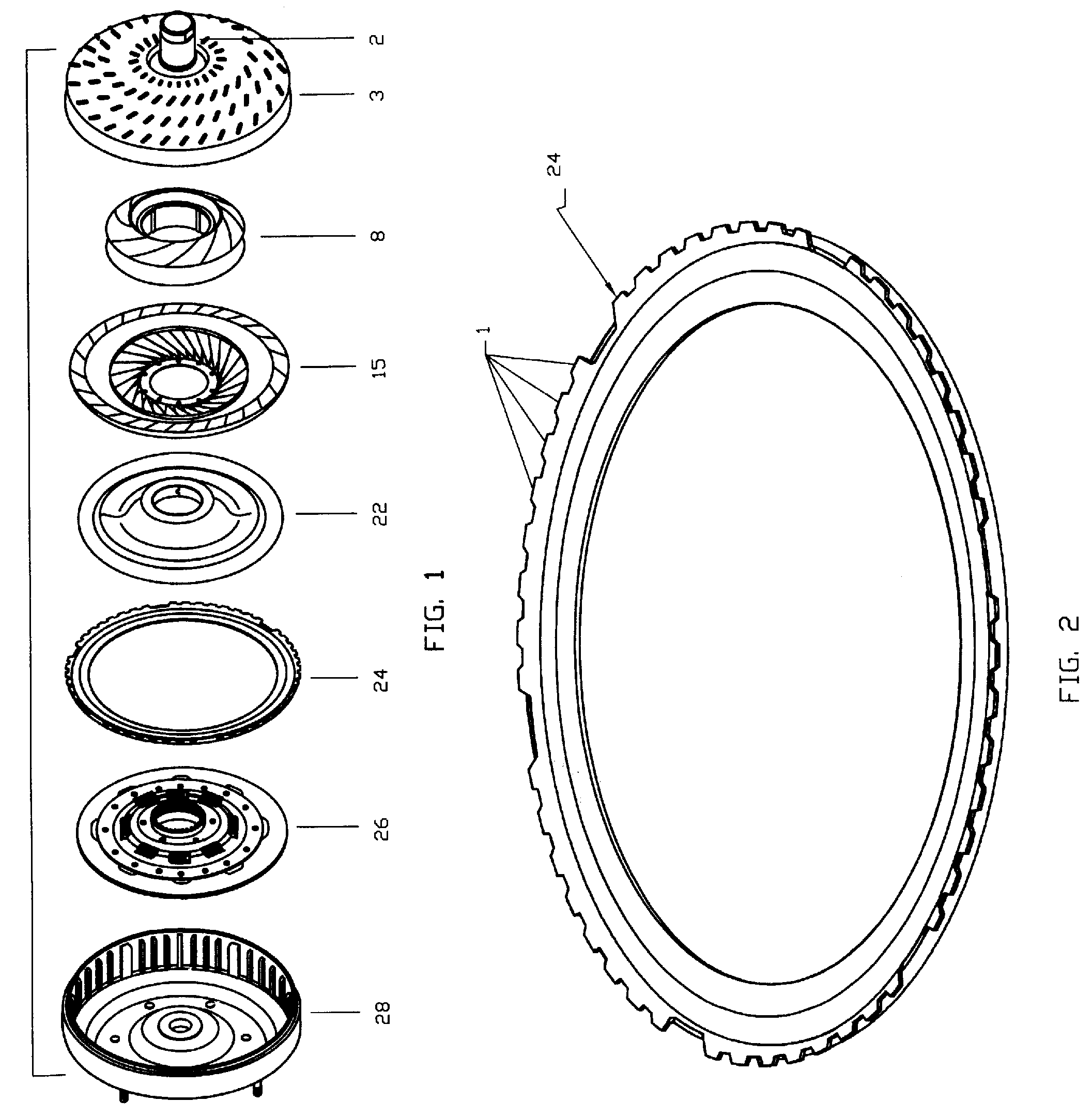
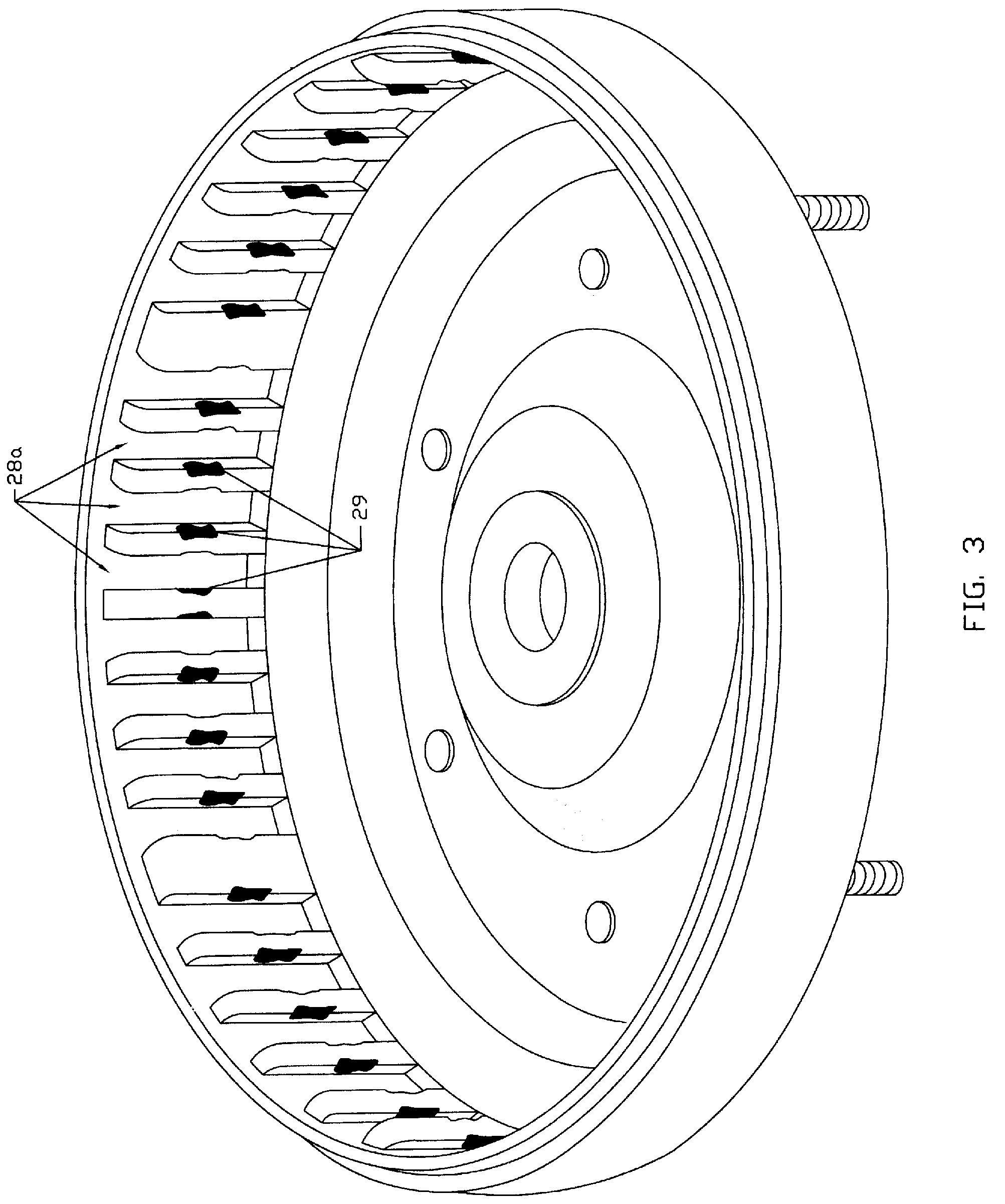
[0028]In a preferred embodiment of the present invention of a wear resistant drive plate or ring, the front of some or all of the teeth of the drive plate are initially formed, such as by stamping, with an extended length and then bent perpendicularly. Alternatively, the bent teeth are formed initially with the formation of the drive plate. The bending of the front of the teeth is in contrast to the bending of the tooth flank as in the prior art. As a result, a much longer drive contact area is formed when compared to that of a typical wear-prone assembly. The amount of tooth extension and upbend in the forward direction away from the plate or ring is essentially unlimited (limited only by channel length and interference with other components), with resultant reduction in concentrated pressure and wear in the assembly. This is effected by converting the scraping contact between drive plate and into a sliding one. Also, with perpendicular elongation of the teeth elements, tilting pla...


PUM


Abstract

A clutch member of a torque converter of an automatic transmission fitted slidingly with a splined connection between a number of extending teeth of the clutch member and channels of a torque converter housing configured to slidingly engage the teeth. At least two of the teeth are elongated for a distance beyond engagement with a base of the respective engaging channels and bent at right angles to the original tooth extension direction. The extent of parallel engagement of the bent tooth and base of the channel of the splined connection is significantly increased and fretting wear between the teeth and the channels of the housing is reduced or eliminated.

Description

FIELD OF THE INVENTION[0001]This invention relates to prevention or reduction of wear inherent in tooth-channel splined engagements and particularly to reduction of fretting of clutch plate configurations.BACKGROUND OF THE INVENTION[0002]Gear teeth are often used in mechanisms, in splined engagement with closely fitting channels, in order to reliably provide axial movement within a drive mechanism base. The splined engagement advantageously permits ready removal of connected components for service and / or parts replacement. Connections between teeth and co-fitting channels generally take advantage of increased surface area contact afforded by multiple toothed engagement and the strength of unitary metal element engagements. Despite such advantages, splined engagements of teeth and channels are subject to lateral wear and tear in the direction of limited axial teeth travel within the channels.[0003]Vehicular clutch drive plates and particularly those used in automotive transmissions a...

Claims


Application Information

Patent Timeline
Patent Type & Authority Applications(United States)
IPC IPC(8): F16D13/60
CPCF16D13/683F16D13/648F16D13/52F16D13/68
Inventor RATNER, MICHAEL
Owner TRI COMPONENT PROD
Why Eureka
Try Eureka