Cooling structure of fuel injection valve

a technology of fuel injection valve and cooling structure, which is applied in the direction of fuel injection apparatus, fuel feed system, engine components, etc., can solve the problem that the metal ring member cannot be installed, and achieve the effect of improving the cooling effect of the fuel injection valve and high load operation

Inactive Publication Date: 2011-03-24
MITSUBISHI HEAVY IND LTD
View PDF9 Cites 1 Cited by
  • Summary
  • Abstract
  • Description
  • Claims
  • Application Information

AI Technical Summary

Benefits of technology

[0027]In view of the problems of the related art, an object of the present invention is to provide a cooling structure of a fuel injection valve which can cope with the high load operation of the engine by transferring heat efficiently from a nozzle to a cylinder head and improving the cooling effect of the fuel injection valve including the nozzle.
[0031]In the example illustrated in FIG. 1, the nozzle nut 3 is not in direct contact with the spacer 15 and the injection valve body 16 is fit into the upper part of the nozzle nut 3 at a screw mounting section 3a to be installed between the injection valve body 16 and the nozzle 1. Therefore, it is efficient to install the metal ring member 10 in the space A of a slit shape that is arranged lower than the spacer 15 so as to efficiently cool the nozzle 1.
[0040]As described above, the heat is transferred from the nozzle to the cylinder head via both the metal gasket and the metal ring member so that in comparison to the conventional fuel injection valve of FIG. 3, a greater temperature drop can be expected and the nozzle can be operated at temperature not higher than the maximum allowable temperature even in the high load operation of the engine and thus the fuel injection valve that can cope with the high load operation of the engine can be obtained.
[0041]Further, unlike a fuel injection valve of a liquid cooling type which performs the cooling of the fuel injection valve by fuel oil or lubricant oil, no complex device such as a cooling passage is needed and the cooling performance of the fuel injection valve is improved at a low cost.
[0042]Furthermore, as a detailed cooling structure of the fuel injection valve, the metal ring member is formed into a ring shape with a hollow space inside such that the outer circumferential face thereof is in contact with the inner circumferential face of the outer sleeve and the inner circumferential face thereof is in contact with the groove arranged in the inner circumferential face of the nozzle nut. With this structure, by changing the shape of the metal ring member, the optimal contact pressure of the inner circumferential face and the outer circumferential face of the ring member can be obtained to transfer heat from the nozzle efficiently.
[0043]Moreover, as another detailed cooling structure of the fuel injection valve, the metal ring member comprises the spring which presses an outer circumference of the metal ring member against the inner circumferential face of the outer sleeve, and the outer circumference of the metal ring member forms the contact face with the inner circumference face of the outer sleeve. With this structure, by adjusting the strength of the spring which presses the contact face of the metal ring member, the optimal contact pressure can be obtained so as to transfer the heat efficiently from the nozzle 1 to the cylinder head side.

Problems solved by technology

For instance, the metal ring member cannot be installed where the circumferential surfaces form a taper shape.

Method used


Image

  • Cooling structure of fuel injection valve
  • Cooling structure of fuel injection valve
  • Cooling structure of fuel injection valve

Examples


first preferred embodiment

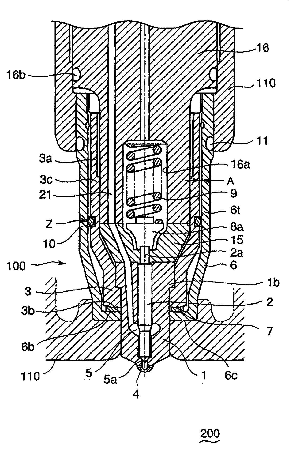
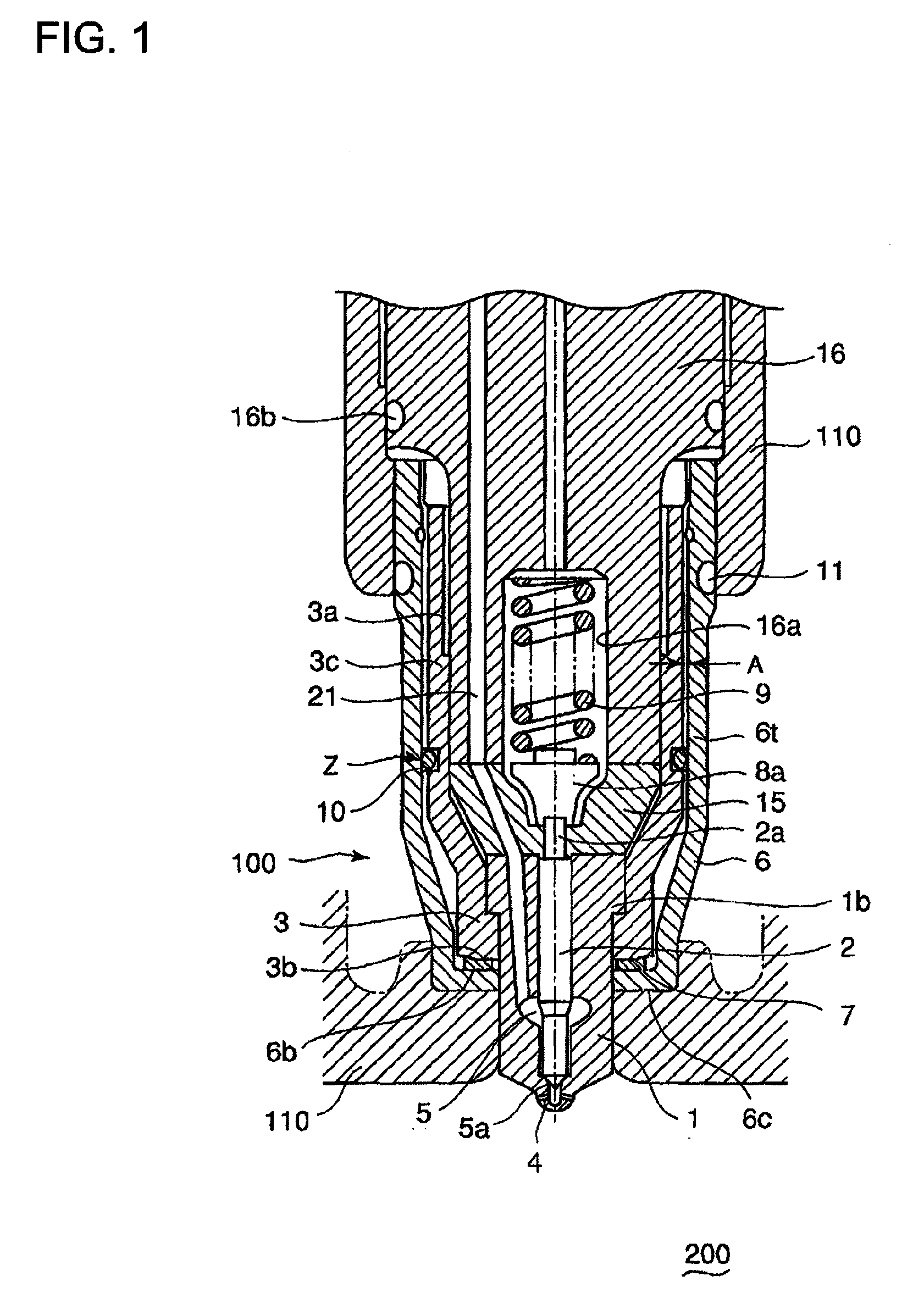
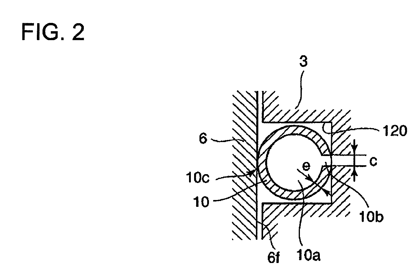
[0049]FIG. 1 is a sectional view of a main part of a fuel injection valve of a diesel engine in relation to a first preferred embodiment of the present invention. FIG. 2 is an enlarged view of a section Z of the first preferred embodiment.

[0050]FIG. 1 shows a fuel injection valve 100 in which a nozzle has an injection hole 4 for injecting fuel at a tip thereof and a needle valve 2 is fit in the nozzle 1 such that the needle valve can reciprocate therein. When there is no injection, the tip of the needle valve 2 is in contact with a seating portion 5a of the nozzle 1 so as to store high-pressure fuel in a fuel storage 5.

[0051]A fuel injection valve body 16 includes a hollow space 16a, and a spring shoe 8a of the nozzle valve is fit in the hollow space 16a at a bottom thereof in such a manner that the spring shoe 8a is in contact with a top end 2a of the needle valve 2.

[0052]Further, a needle valve spring 9 is interposed in the hollow space 16a between the spring shoe 8a and the injec...

second preferred embodiment

[0070]A second preferred embodiment of the present invention is different from FIG. 1 in the configuration of the metal ring member.

[0071]FIG. 3 is an enlarged view of a section Z of a second preferred embodiment.

[0072]In FIG. 3, a metal ring member 10s is formed into a ring shape with a notched portion in an outer circumference thereof like a piston ring. The cross sectional shape of the metal ring member 10s is square. The metal ring member 10s is inserted in the groove 120 such that the outer part thereof touches the inner circumferential face 6f of the outer sleeve 6 to form a contact face 10m.

[0073]Furthermore, a spring 13 for pressing the contact face 10m against the inner circumferential face 6f of the outer sleeve 6 and another spring 12, e.g. a plate type spring for pressing the ring member 10s in the length direction thereof.

[0074]In this manner, by adjusting the strength of the springs 12 and13 which press the contact face 10m of the metal ring member 10s, the optimal co...


PUM


Abstract

The present invention provides a cooling structure of a fuel injection valve that can cope with the high load operation of the engine by efficiently transferring heat from a nozzle to a cylinder head, thereby improving the cooling efficiency of the injection valve including the nozzle valve. In the cooling structure, fuel is injected through an injection hole by opening and closing of the needle valve 2 that is reciprocatably fit inside the nozzle and removably attached to a seating portion of the nozzle at a tip. The cooling structure comprises a metal ring member 10 which is interposed between an outer circumferential face of the nozzle nut 3 and an inner circumferential face of the outer sleeve 6 so as to transfer heat from the nozzle 1 to the cylinder head 110 via the nozzle nut 3 and the outer sleeve 6.

Description

BACKGROUND OF THE INVENTION[0001]1. Field of the Invention[0002]The present invention mainly relates to a cooling structure of a fuel injection valve to be applied to a diesel engine.[0003]2. Description of the Related Art[0004]FIG. 4 is a sectional view of a relevant part of a conventional fuel injection valve of a diesel engine.[0005]FIG. 4 shows a fuel injection valve 100 in which a nozzle has an injection hole for injecting fuel at a tip thereof and a needle valve 2 is fit in the nozzle 1 such that the valve can reciprocate therein. When there is no injection, the tip of the needle valve 2 is in contact with a seating portion of the nozzle 1 so as to store high-pressure fuel in a fuel storage 5.[0006]A fuel injection valve body 16 includes a hollow space 16a and a spring shoe 8a of the nozzle valve is fit in the hollow space at a bottom thereof in such a manner that the spring shoe 8a is in contact with a top end 2a of the needle valve 2.[0007]Further, a needle valve spring 9 is...

Claims


Application Information

Patent Timeline
Patent Type & Authority Applications(United States)
IPC IPC(8): B05B15/00
CPCF02M61/14F02M53/043
Inventor TSUKAMOTO, TARO
Owner MITSUBISHI HEAVY IND LTD
Why Eureka
Try Eureka