
GNSS ultra-short baseline heading determination system and method

a baseline and ultra-short technology, applied in the field of navigation and positioning systems, can solve the problems of inability to function correctly, gyro-compass can be subject to errors, and magnetic compass is subject to several limitations

Active Publication Date: 2011-03-24
APPAREO SYST
View PDF4 Cites 19 Cited by
  • Summary
  • Abstract
  • Description
  • Claims
  • Application Information

AI Technical Summary

Benefits of technology

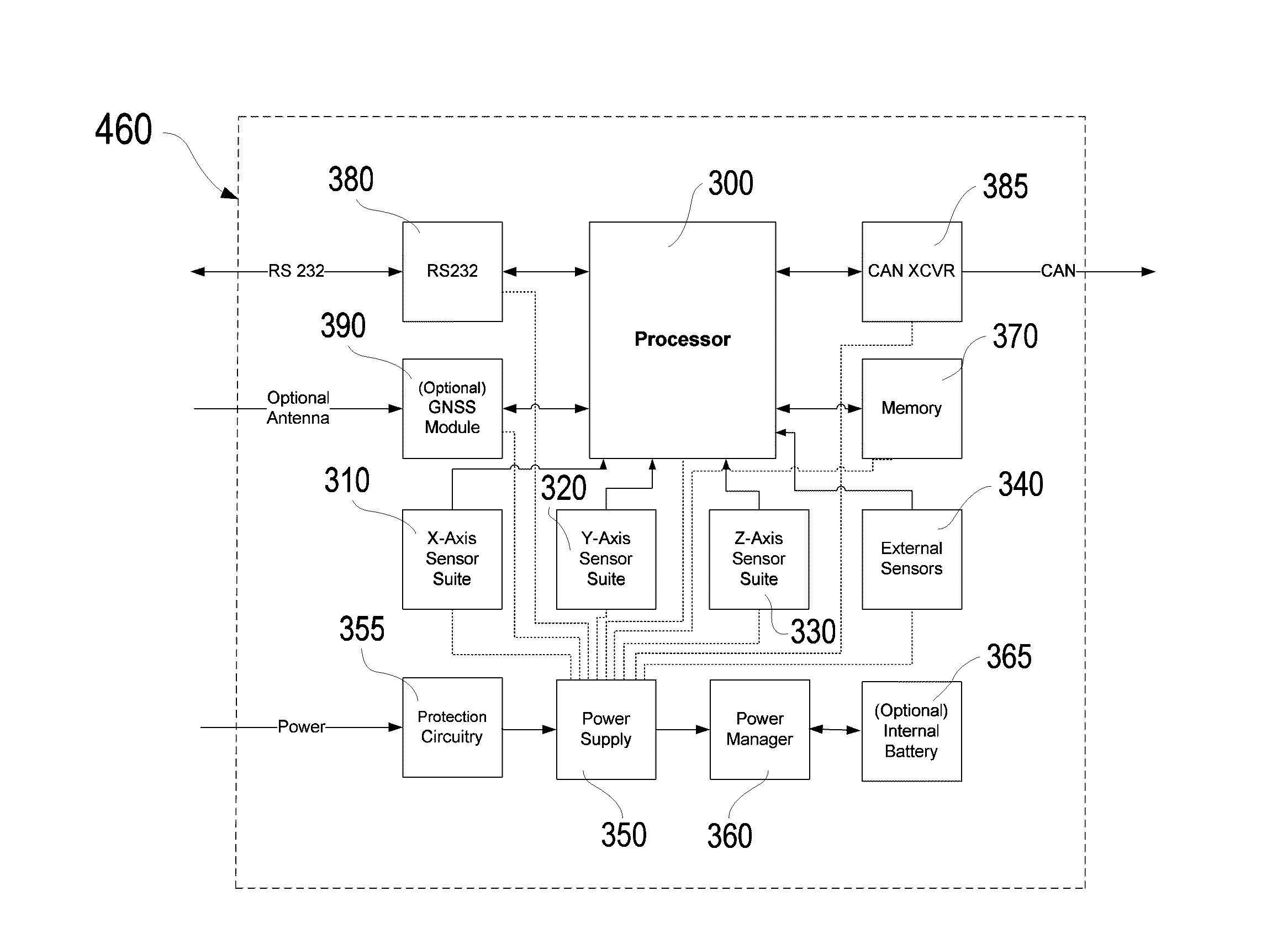
[0013]According to one aspect of the present invention, a heading determination system is comprised of an inertial measurement unit coupled with at least two GNSS receivers, each receiver paired with and receiving signals from a corresponding GNSS antenna, wherein the GNSS antennas are separated by an ultra-short baseline. The heading determination system receives signals broadcast by a plurality of GNSS satellites and calculates the phase difference in the signal seen among the separate GNSS antennas. Using this phase difference information, derived from comparing the signals received from a plurality of pairs of GNSS satellites, along with attitude data generated by the inertial measurement unit, the heading determination system calculates a highly-accurate heading solution.
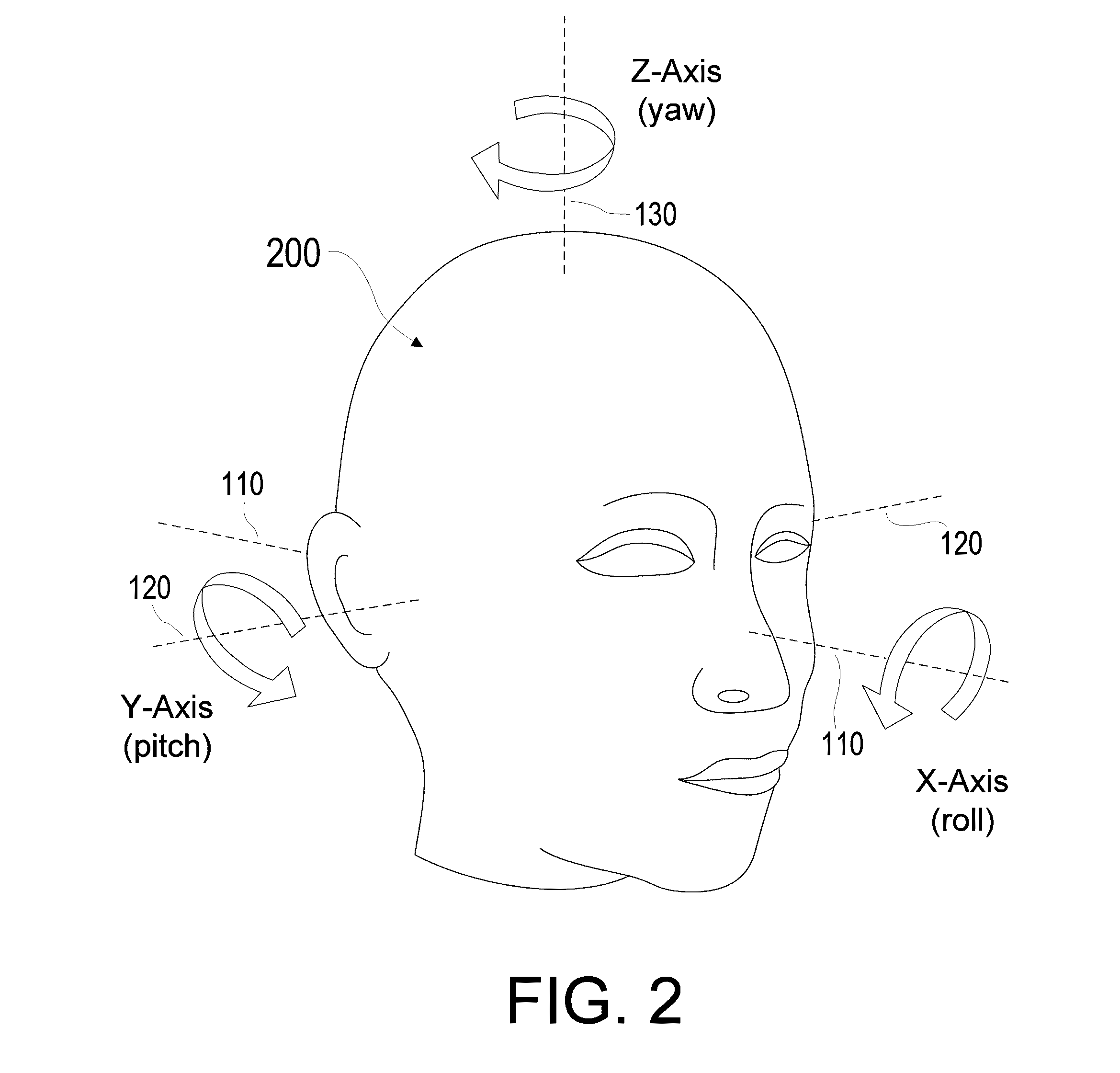
[0014]According to another aspect of the present invention, a heading determination system takes the form of an apparatus worn on the human head, such as a helmet, headphones, or any other type of mounting to a human head, wherein a first GNSS receiver is mounted to a first side of the apparatus and a second GNSS receiver is mounted to a second side of the apparatus, and an inertial measurement unit is mounted in the center of the apparatus, near the top of the head as worn by a user. The effective baseline width between the first GNSS receiver and the second GNSS receiver is variable, and depends on the shape and size of the head on which it is being worn, and so a means of determining the baseline width after it is in place is provided. This calculated baseline width is used in the calculation of a highly-accurate heading solution.
[0015]According to yet another aspect of the present invention, a heading determination system takes the form of a module or series of modules which may be rigidly mounted in a fixed configuration to a vehicle or platform, wherein a first GNSS receiver is mounted in a first fixed location relative to a second GNSS receiver in a second fixed location, separated by an ultra-short baseline, and an inertial measurement unit is mounted in a third fixed location relative to the first and second GNSS receiver locations. The heading determination system uses phase difference information derived from comparing the signals received from the GNSS satellites, along with attitude data generated by the inertial measurement unit, to calculate a highly-accurate heading solution.

Problems solved by technology

Unfortunately, a magnetic compass is subject to several limitations.
Because the operation of a gyro-compass depends on the rotation of the Earth, it will not function correctly if the vehicle or body to which it is mounted is moving fast in an east to west direction.
The gyro-compass can be subject to errors caused by rapid changes in course, and the gyro-compass is subject to drift because of inertial effects on its mechanical parts and electrical measurement imperfections.
However, ring laser gyroscopes and fiber optic gyroscopes are very expensive systems and therefore do not work well for all applications.
In particular, building a head- or human-mounted heading determination system based on a ring laser gyroscope or similar system would not be practical or affordable.
However, GNSS-based systems using a single receiver and single antenna do not work when the vehicle or body is not moving.
For example, if a helicopter is hovering in one spot (one GNSS location) for a period of time, there is no way to determine what direction that helicopter is currently pointed, as there is no movement from one spot to another with which to determine heading.
Similarly, a head- or human-mounted GNSS system with a single receiver and single antenna cannot determine the human's heading when the human is standing in one spot.
There is no way to tell which way the human is looking if they are not moving.
However, these two-antenna systems are typically intended to be mounted in a known orientation and are subject to the affects of roll and pitch as the vehicle or body to which the system is mounted moves in space.
It is very difficult to obtain a highly-accurate heading using a two-antenna GNSS system unless there is some mechanism for compensating for roll and pitch and other movements.

Method used


Image

  • GNSS ultra-short baseline heading determination system and method
  • GNSS ultra-short baseline heading determination system and method
  • GNSS ultra-short baseline heading determination system and method

Examples


Embodiment Construction

[0041]With reference now to the drawings, and in particular to FIGS. 1 through 14 thereof, a new ultra-short baseline (USBL) heading determination method and system embodying the principles and concepts of the present invention will be described.

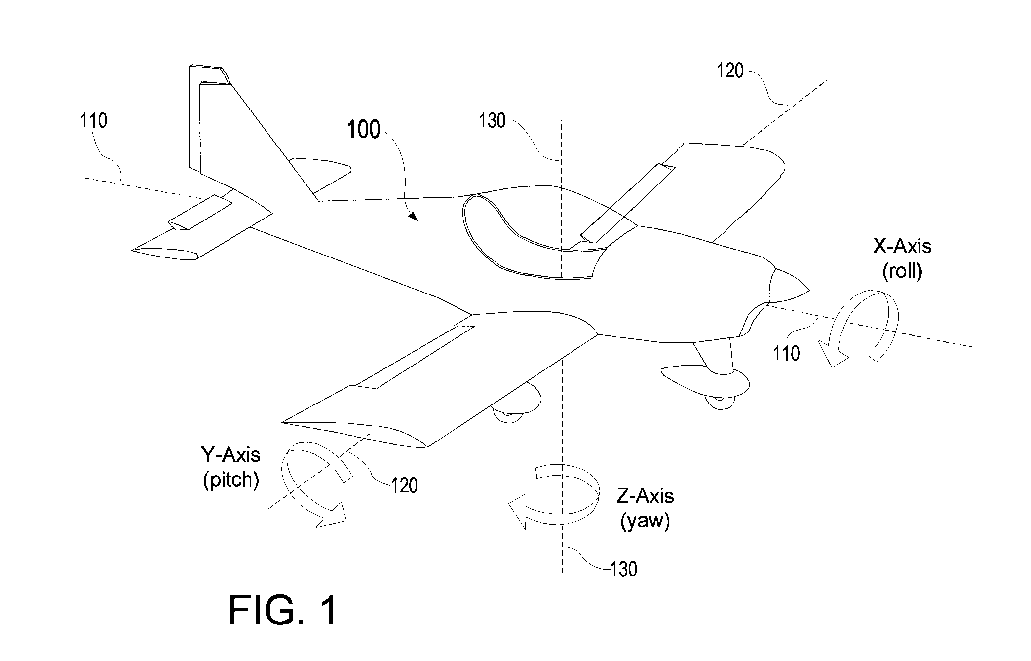
[0042]FIG. 1 illustrates the rotational axes considered when calculating a position, orientation, and heading solution for a vehicle 100 such as an aircraft. A vehicle 100 in motion is capable of rotation about three axes. The axis extending longitudinally through the length of the vehicle 100 from the nose (front) to its tail (back) is considered to be the x-axis 110. When the vehicle 100 rotates about the x-axis 110, the vehicle 100 is said to be experiencing “roll”. The axis extending laterally through the vehicle 100, from one side to the other side (for example, from one wing to the other wing on an aircraft) is considered to be the y-axis 120. When the vehicle 100 rotates about the y-axis 120, the vehicle 100 is said to be experiencing...


PUM


Abstract

A heading determination system comprises an inertial measurement unit (IMU) coupled with at least two GNSS receivers, each receiver paired with and receiving signals from a corresponding GNSS antenna, wherein the GNSS antennas are separated by an ultra-short baseline. The heading determination system receives signals broadcast by a plurality of GNSS satellites and calculates the phase difference in the signal seen among the separate GNSS antennas. Using this phase difference information, derived from comparing the signals received from a plurality of GNSS satellites, along with attitude data generated by the IMU, the heading determination system calculates a highly-accurate heading solution. A method is provided for determining a heading of a system including an IMU coupled with at least two GNSS receivers, with each receiver being paired with and receiving signals from a corresponding GNSS antenna and the antennas being separated by an ultra-short baseline.

Description

BACKGROUND OF THE INVENTION[0001]1. Field of the Invention[0002]This invention relates to navigation and positioning systems, and more particularly to a system and method for calculating highly accurate heading information through the use of multiple GNSS receivers separated by a short distance.[0003]2. Description of the Related Art[0004]Systems for determining the heading of a moving body, such as a vehicle or a person, exist in the prior art. One such system is a magnetic compass, which is a navigational instrument for determining direction relative to the Earth's magnetic field. It typically consists of some form of freely-rotating magnetized pointer that can align itself with the Earth's magnetic field. However, solid state versions of the magnetic compass also exist, wherein solid state magnetic sensors are used to sense the compass's orientation relative to the Earth's magnetic field. In its original form, the magnetic compass is one of the oldest and least complex navigation...

Claims


Application Information

Patent Timeline
IPC IPC(8): G01S19/53
CPCG01S19/55G01S19/35G01C21/165A61B2018/206
Inventor ZIETZ, JOHN M.ALLEN, ROBERT M.WEINMANN, ROBERT V.
Owner APPAREO SYST
Learn More