
Liquid crystal display

a liquid crystal display and display technology, applied in non-linear optics, instruments, optics, etc., can solve the problems of increasing manufacturing costs and complicated structures, and achieve the effect of reducing manufacturing costs and simplifying structures

Active Publication Date: 2011-03-24
SAMSUNG DISPLAY CO LTD
View PDF13 Cites 5 Cited by
  • Summary
  • Abstract
  • Description
  • Claims
  • Application Information

AI Technical Summary

Benefits of technology

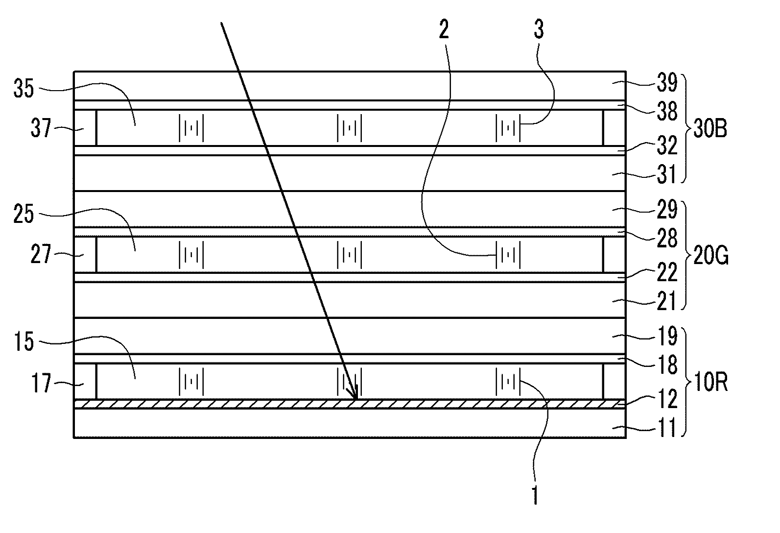
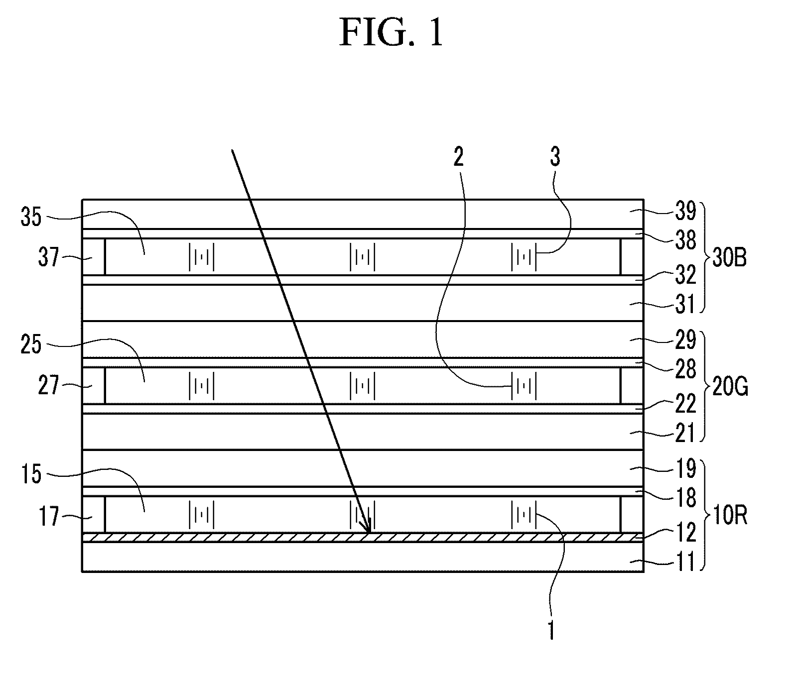
[0009]These and other needs are addressed by the present invention, in which exemplary embodiments provide to simplify a structure and to reduce manufacturing costs of a cholesteric liquid crystal display by forming an electrode as a carbon nanotube without using a light absorption layer.

Problems solved by technology

However, the electrophoretic display has some drawbacks, for example, to realize full colors when red, green, and blue cholesteric LCs having different helical pitches are deposited in the cholesteric liquid crystal display.
As such, the cholesteric liquid crystal display has a bi-stability which rest in two states such that it has low power consumption compared with the other display devices, however an additional light absorption layer should be added to realize the black state that makes the structure complicated and increases its manufacturing costs.

Method used


Image

  • Liquid crystal display
  • Liquid crystal display
  • Liquid crystal display

Examples


Embodiment Construction

[0021]A liquid crystal display and method of manufacturing a liquid crystal display are disclosed. In the following description, for the purposes of explanation, numerous specific details are set forth in order to provide a thorough understanding of the present invention. It is apparent, however, to one skilled in the art that the present invention may be practiced without these specific details or with an equivalent arrangement. In other instances, well-known structures and devices are shown in block diagram form in order to avoid unnecessarily obscuring the present invention.

[0022]It is understood that when an element such as a layer, a film, a region, or a substrate is referred to as being “on” an element, it can be directly on the element, over the element, or intervening elements may also be present. In contrast, when an element is referred to as being “directly on” another element, there are no intervening elements present.

[0023]Now, a liquid crystal display according to exemp...


PUM

PropertyMeasurementUnit
transmittanceaaaaaaaaaa
red wavelengthaaaaaaaaaa

Abstract

A liquid crystal display according to exemplary embodiments of the present invention includes a first panel including a first lower substrate, a first lower electrode formed on the first lower substrate, a first upper substrate facing the first lower substrate, a first upper electrode formed on the first upper substrate, and a first cholesteric liquid crystal injected between the first lower electrode and the first upper electrode, wherein the first lower electrode includes carbon nanotubes. The liquid crystal display including the first lower electrode made of the carbon nanotubes without a light absorption layer provides a simple structure capable of realizing a black state.

Description

CROSS-REFERENCE TO RELATED APPLICATION[0001]This application claims priority from and the benefit of Korean Patent Application No. 10-2009-0090259 filed on Sep. 23, 2009, which is hereby incorporated by reference for all purposes as if fully set forth herein.BACKGROUND OF THE INVENTION[0002]1. Field of the Invention[0003]Exemplary embodiments of the present invention relate to a liquid crystal display and method for manufacturing a liquid crystal display device.[0004]2. Description of the Background[0005]As currently popular flat panel displays, there are a liquid crystal display (LCD), a plasma display device (PDP), an organic light emitting device (OLED), a field effect display (FED), and an electrophoretic display device.[0006]Among them, the liquid crystal display has been widely adopted as a monitor and a television, the plasma display device has been adopted as a large size television, and the organic electric field emissive display device has been adopted for a mobile phone d...

Claims


Application Information

Patent Timeline
Patent Type & Authority Applications(United States)
IPC IPC(8): G02F1/1347G02F1/1343G02F1/13
CPCG02F1/13454G02F1/1343G02F1/1347
Inventor KIM, JONG-SEONGROH, NAM-SEOKKIM, SANG-IILEE, WOO-JAE
Owner SAMSUNG DISPLAY CO LTD
Learn More