Optical system for camera

a technology of optical system and camera, applied in the field of optical system for camera, can solve the problems of deteriorating design flexibility of optical system, difficult to meet the optical performance, and the size of the optical system mounted in the mobile communication device, so as to improve the design flexibility, reduce the size of the first lens, and improve the effect of adjacent aberration characteristics including astigmatism and distortion aberration

Active Publication Date: 2011-03-24
SAMSUNG ELECTRO MECHANICS CO LTD
View PDF3 Cites 14 Cited by
  • Summary
  • Abstract
  • Description
  • Claims
  • Application Information

AI Technical Summary

Benefits of technology

[0023]As described above, in accordance with an embodiment of the present invention, it is possible to implement a compact optical system for a camera to which a mobile communication terminal can be applied through improving design flexibility by configuring all four lenses with aspheric plastic lenses while adopting four lenses in an optical system for a camera.
[0024]Further, the present invention is suitable for designing a

Problems solved by technology

As such, a plurality of lenses are used for the optical system to maintain high resolution and the optical system is preferably configured by using a glass lens having high optical transmittance and a high refractive index, but the optical system mounted in the mobile communication device is difficult to satisfy conditions of the decrease in size and the decrease in cost as a design of the optical system by characteristics of the optical system.
Therefore, the optical system mounted in the mobile communication device uses a plastic lens which can be easily molded and reduces the number of lenses as possible in order

Method used


Image

  • Optical system for camera
  • Optical system for camera
  • Optical system for camera

Examples


first embodiment

[0073]Table 1 shown below shows a value example in accordance with the first embodiment of the present invention.

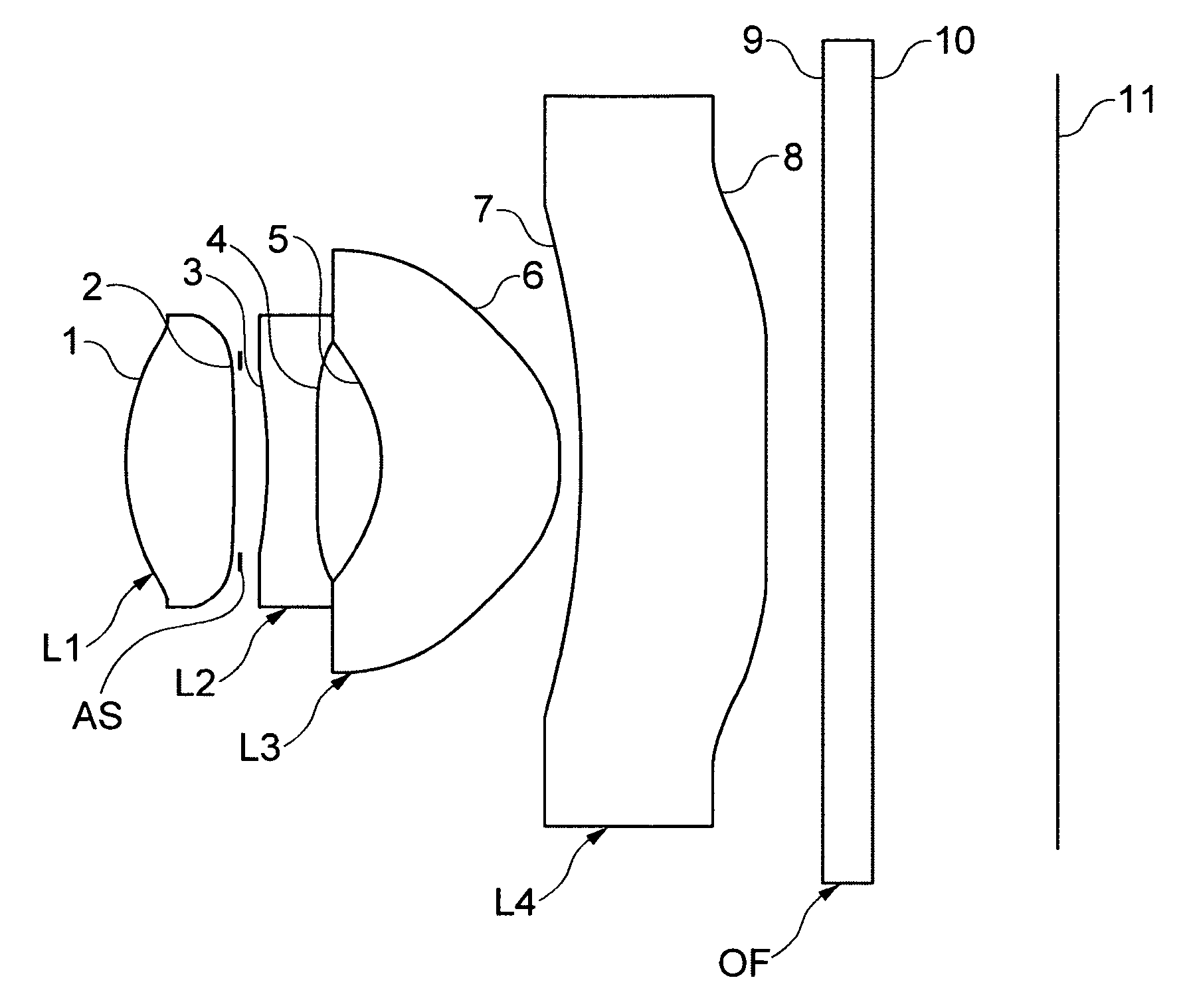
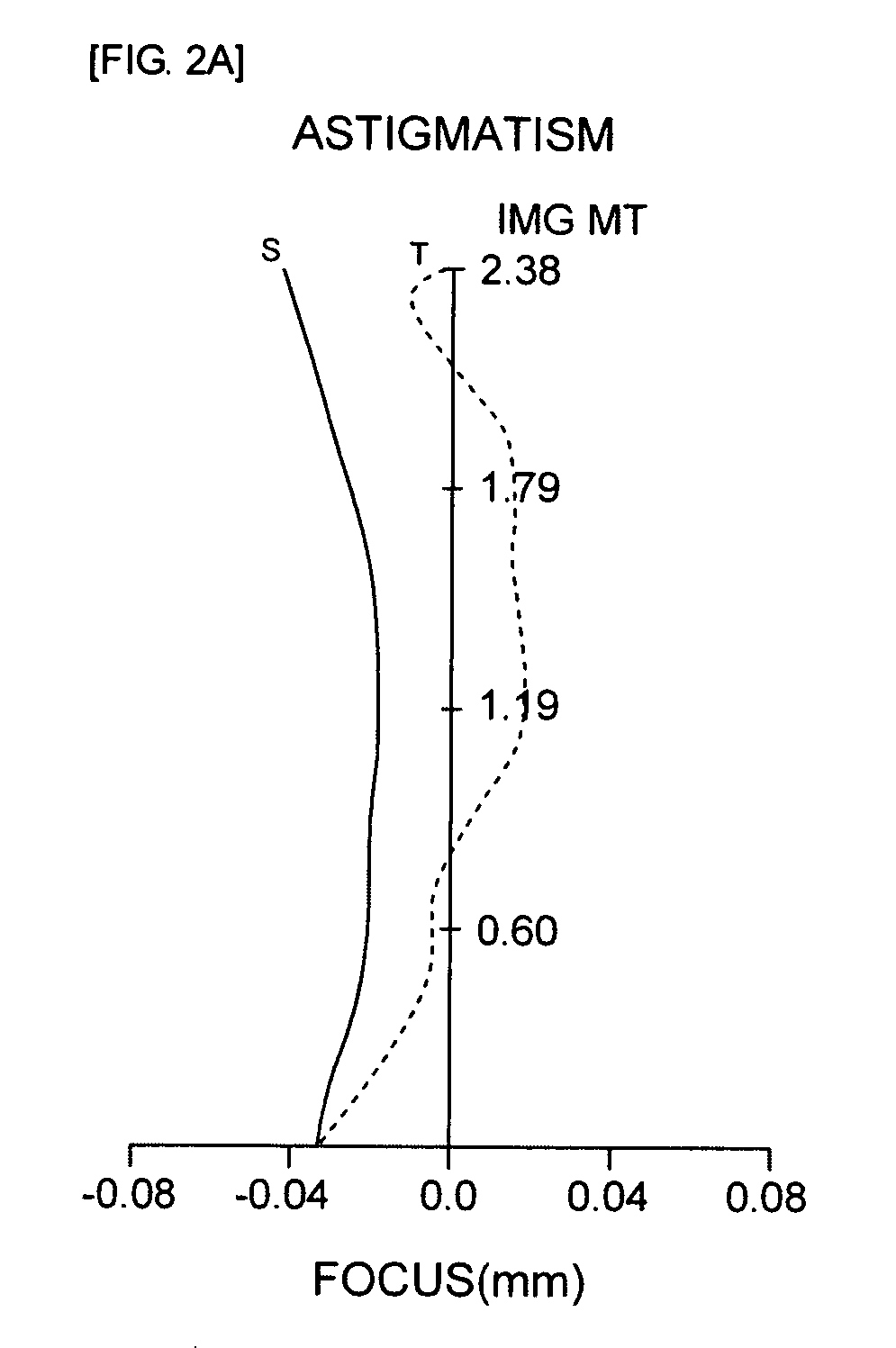
[0074]Further, FIG. 1 is a configuration diagram showing a configuration of lenses of an optical system for a camera in accordance with a first embodiment of the present invention, FIGS. 2A and 2B show astigmatism and distortion aberration of an optical system shown in Table 1 and FIG. 1, respectively, and FIGS. 3A to 3D are diagrams of coma aberration for each field in accordance with a first embodiment. In addition, in the astigmatism diagram of FIG. 2A, ‘S’ represents sagital and T represents tangential.

[0075]In the first embodiment, a view angle is 64 degrees, a distance TL from an object-side surface 1 to the top surface of the first lens L1 is 4.2 mm, and an effective focus distance f of the entire optical system is 3.6 mm. Further, the first lens L1 to the fourth lens L4 all are configured by plastic lenses.

TABLE 1AbbeSurfaceCurvatureThickness orRefractiveNumberNum...

second embodiment

[0078]Table 3 shown below shows a value example in accordance with the second embodiment of the present invention.

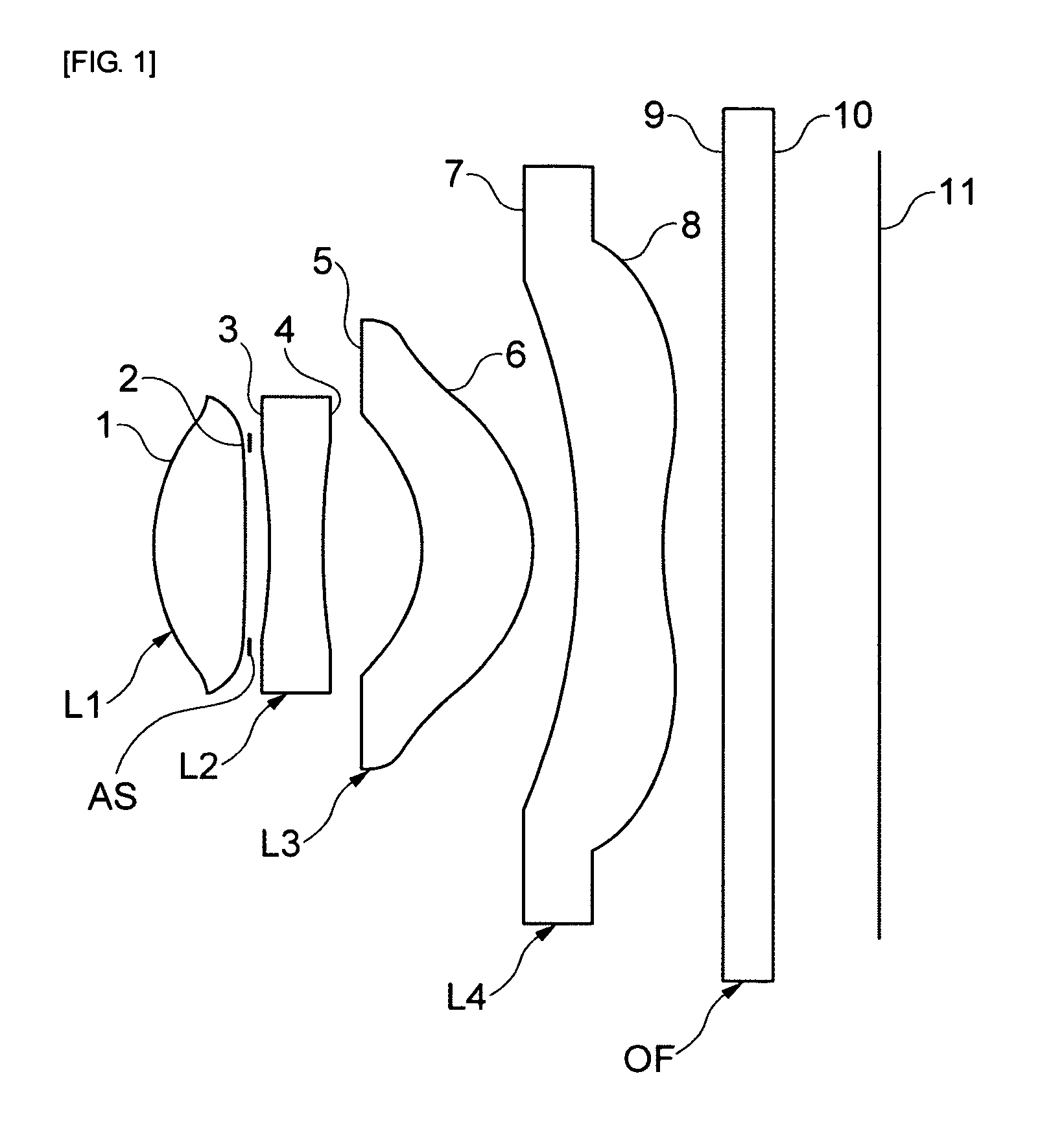
[0079]Further, FIG. 4 is a configuration diagram showing a configuration of lenses of an optical system for a camera in accordance with a second embodiment of the present invention, FIGS. 5A and 5B show astigmatism and distortion aberration of an optical system shown in Table 3 and FIG. 4, respectively, and FIGS. 6A to 6D are diagrams of coma aberration for each field in accordance with a second embodiment. In addition, in the astigmatism diagram of FIG. 5A, ‘S’ represents sagital and ‘T’ represents tangential.

[0080]In the second embodiment, the view angle is 50 degrees, the distance TL from the object-side surface 1 to the top surface of the first lens L1 is 5.5 mm, and the effective focus distance f of the entire optical system is 5.5 mm. Further, the first lens L1 to the fourth lens L4 all are configured by the plastic lenses.

TABLE 3AbbeSurfaceCurvatureThickness orRef...

third embodiment

[0083]Table 5 shown below shows a value example in accordance with the third embodiment of the present invention.

[0084]Further, FIG. 7 is a configuration diagram showing a configuration of lenses of an optical system for a camera in accordance with a third embodiment of the present invention, FIGS. 8A and 8B show astigmatism and distortion aberration of an optical system shown in Table 5 and FIG. 7, respectively, and FIGS. 9A to 9D are diagrams of coma aberration for each field in accordance with a third embodiment. In addition, in the astigmatism diagram of FIG. 8A, ‘S’ represents sagital and ‘T’ represents tangential.

[0085]In the third embodiment, the view angle is 60 degrees, the distance TL from the object-side surface 1 to the top surface of the first lens L1 is 3.8 mm, and the effective focus distance f of the entire optical system is 3.8 mm. Further, the first lens L1 to the fourth lens L4 all are configured by the plastic lenses.

TABLE 5AbbeSurfaceCurvatureThickness orRefract...


PUM


Abstract

The present invention relates to an optical system for a camera.
The optical system for a camera in accordance with the present invention includes: a first lens that has a positive refractive index and has a convex shape toward an object; a second lens that has a negative refractive index and has a concave shape at both surfaces; a third lens that has the positive refractive index and has the convex shape upwards; and a fourth lens that has the negative refractive index and has a concave surface on an object-side surface, and has at least one inflection point on an image surface. It is possible to implement a compact optical system for a camera which can be applied to a mobile communication terminal by improving design flexibility.

Description

CROSS-REFERENCE TO RELATED APPLICATIONS[0001]This application claims the benefit of Korean Patent Application No. 10-2008-0089592 filed with the Korea Intellectual Property Office on Sep. 22, 2009, the disclosure of which are incorporated herein by reference.BACKGROUND OF THE INVENTION[0002]1. Field of the Invention[0003]The present invention relates to an optical system for a camera and, more particularly, to an optical system for a camera in which an aperture stop is disposed between lenses and all lenses constituting the optical system are configured by aspheric plastic lenses.[0004]2. Description of the Related Art[0005]In recent years, as mobile communication devices such as a mobile communication terminal, a PDA, and a smart phone are increased in the quantity thereof and a service provided through a communication technology becomes various, various types of additional functions are provided in addition to a basic communication function.[0006]Among them, a camera module is ess...

Claims


Application Information

Patent Timeline
IPC IPC(8): G02B9/34
CPCG02B13/004G02B9/34G02B13/18
Inventor JO, YONG JOO
Owner SAMSUNG ELECTRO MECHANICS CO LTD
Why Eureka
Try Eureka