

Strain Relief Device and Method for Fiber Optic Cables
a strain relief device and cable technology, applied in the direction of cables, insulated conductors, instruments, etc., can solve the problems of damage to the optical fibers, the cable is not suitable for multiple cables without inserts or other secondary pieces, and the force may strain the optical fibers and the connections attached to the ends of the optical fibers, etc., to achieve the effect of shortening the length of the strap
- Summary
- Abstract
- Description
- Claims
- Application Information
AI Technical Summary
Benefits of technology
Problems solved by technology
Method used
Image

Examples
Embodiment Construction
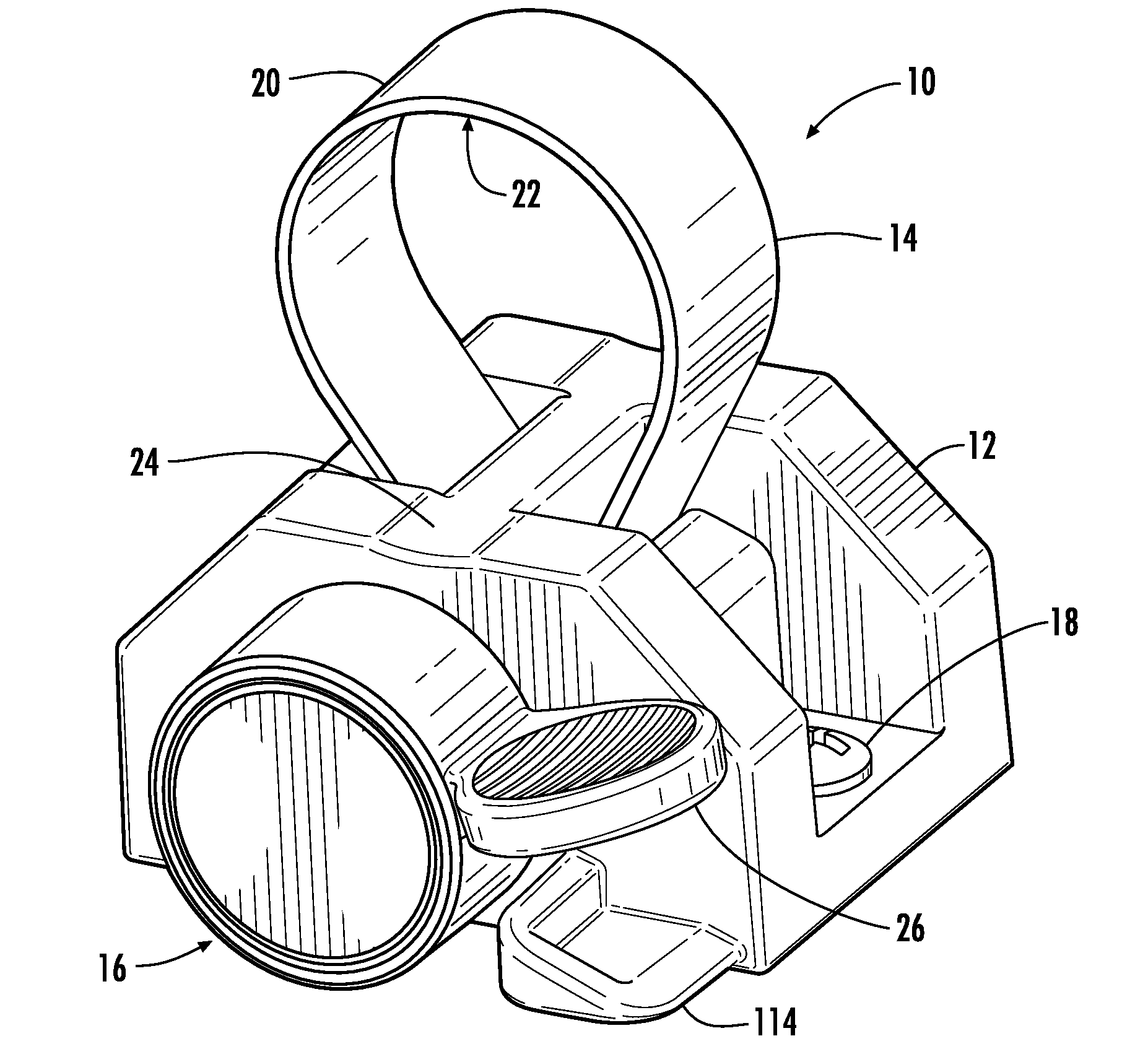
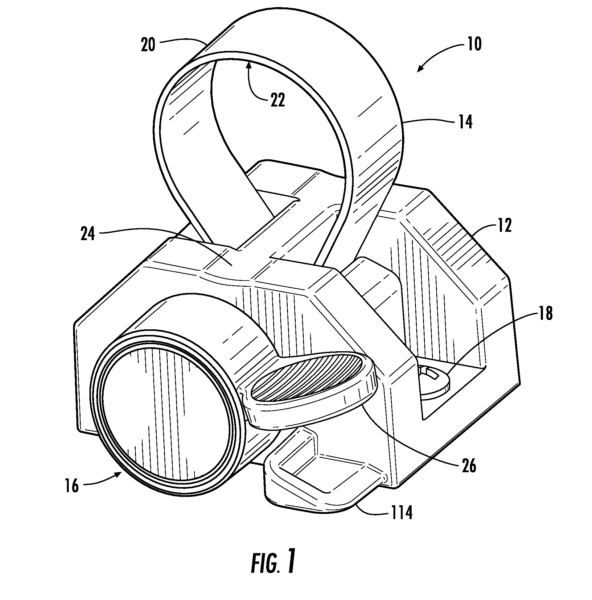
[0006]Embodiments disclosed in the detailed description include devices and methods for strain relieving a fiber optic cable. In one embodiment there is provided a fiber optic cable strain relief device comprising a base, a length of strap and a strap tightener. The length of strap positions in the base and is adapted to at least partially encircle a cable, such as, for example, a fiber optic cable, positioned at the base. A strap tightener is configured to shorten the length of strap in incremental steps, tightening the length of strap encircling the cable. In this way strain relief may be provided to the cable. A release operates to allow the strap to be loosened from around the fiber optic cable.
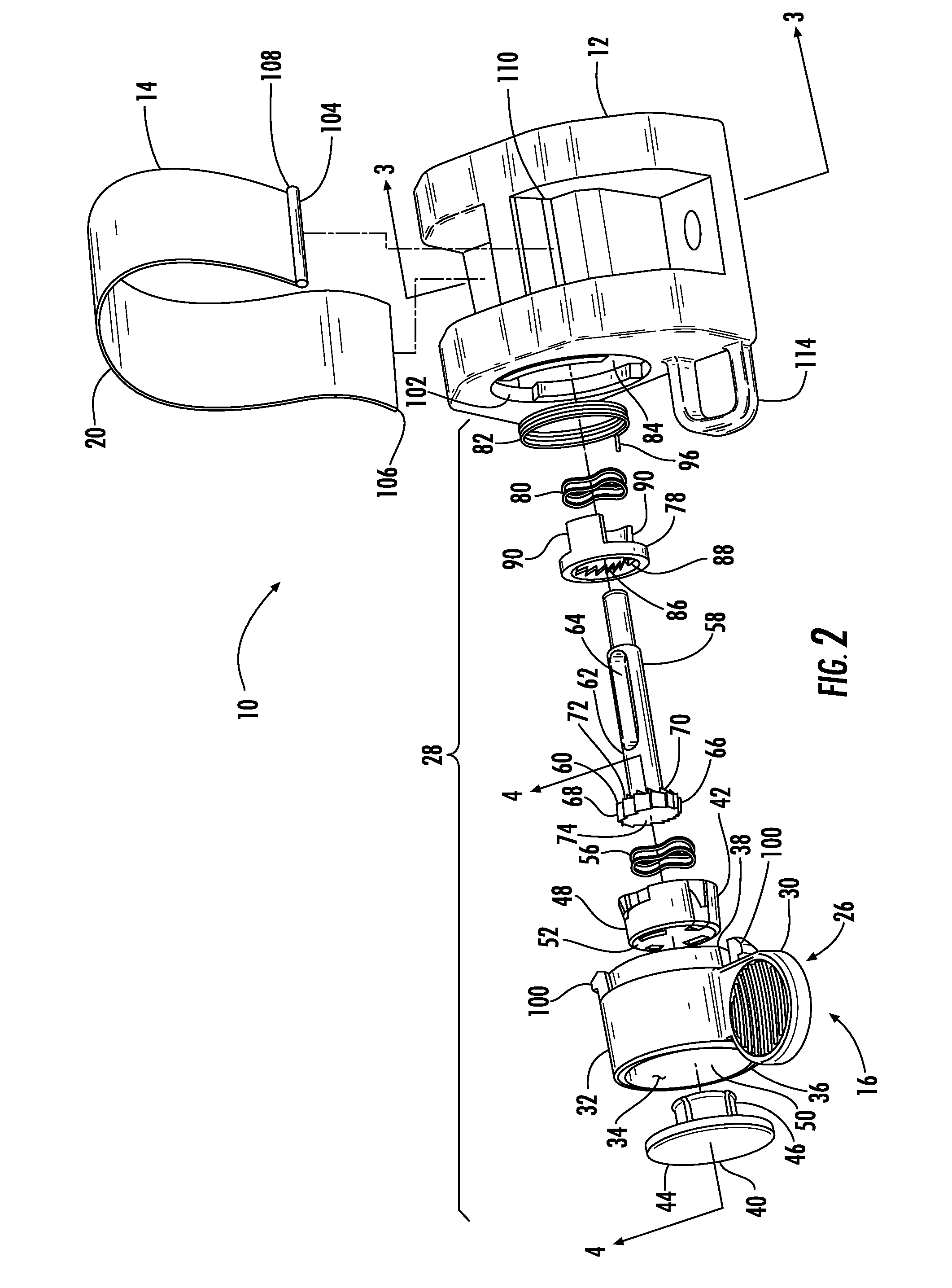
[0007]In one embodiment, there is provided a fiber optic cable strain relief device, comprising a base, a length of strap positioned in the base and forming a loop and a ratchet assembly. The loop is adapted to at least partially encircle a cable positioned at the base. The ratchet assemb...
PUM
 Abstract
Description
Claims
Application Information