Optical free space data transmission

a data transmission and optical free space technology, applied in the field of aircraft data communication systems, can solve the problems of coherent light, increased electromagnetic interference (emi) load and strain on the health of passengers and crew members, and less flexibility of wired signal transmission regarding aircraft cabin (re-) configuration, etc., and achieves the effect of simple reconfiguration

Inactive Publication Date: 2011-03-24
AIRBUS OPERATIONS GMBH
View PDF10 Cites 23 Cited by
  • Summary
  • Abstract
  • Description
  • Claims
  • Application Information

AI Technical Summary

Benefits of technology

[0005]There may be a need to provide an aircraft communication system which allows a simple reconfiguration without EMI.

Problems solved by technology

The wired signal transmission is less flexible regarding aircraft cabin (re-) configuration, short time customer requests and lead-time with respect to additional weight, costs and design effort in comparison to an aircraft with standard equipment.
The signal transmission within an aircraft cabin that is based on wireless RF technologies may generate additional electromagnetic interference (EMI) load and strain for health of passengers and crew members.
Coherent light faces the problems of high directionality and low spatial coverage, eye-safety issues and high costs which can be avoided by non-coherent light.
Non-coherent light sources by nature disallow the use of phase information for data modulation (i.e. complex valued signals cannot be transmitted directly).

Method used


Image

  • Optical free space data transmission
  • Optical free space data transmission
  • Optical free space data transmission

Examples


Embodiment Construction

[0065]In the following, the term “optical access point (OAP)” may correspond to the term “first sending unit”, an OAP may further comprise a second receiver. There may exist a plurality of OAPs. The term “optical terminal / transceiver (OT)” may correspond to the term “first receiving unit”, an OT may comprise a second sender unit. There may exist a plurality of OTs.

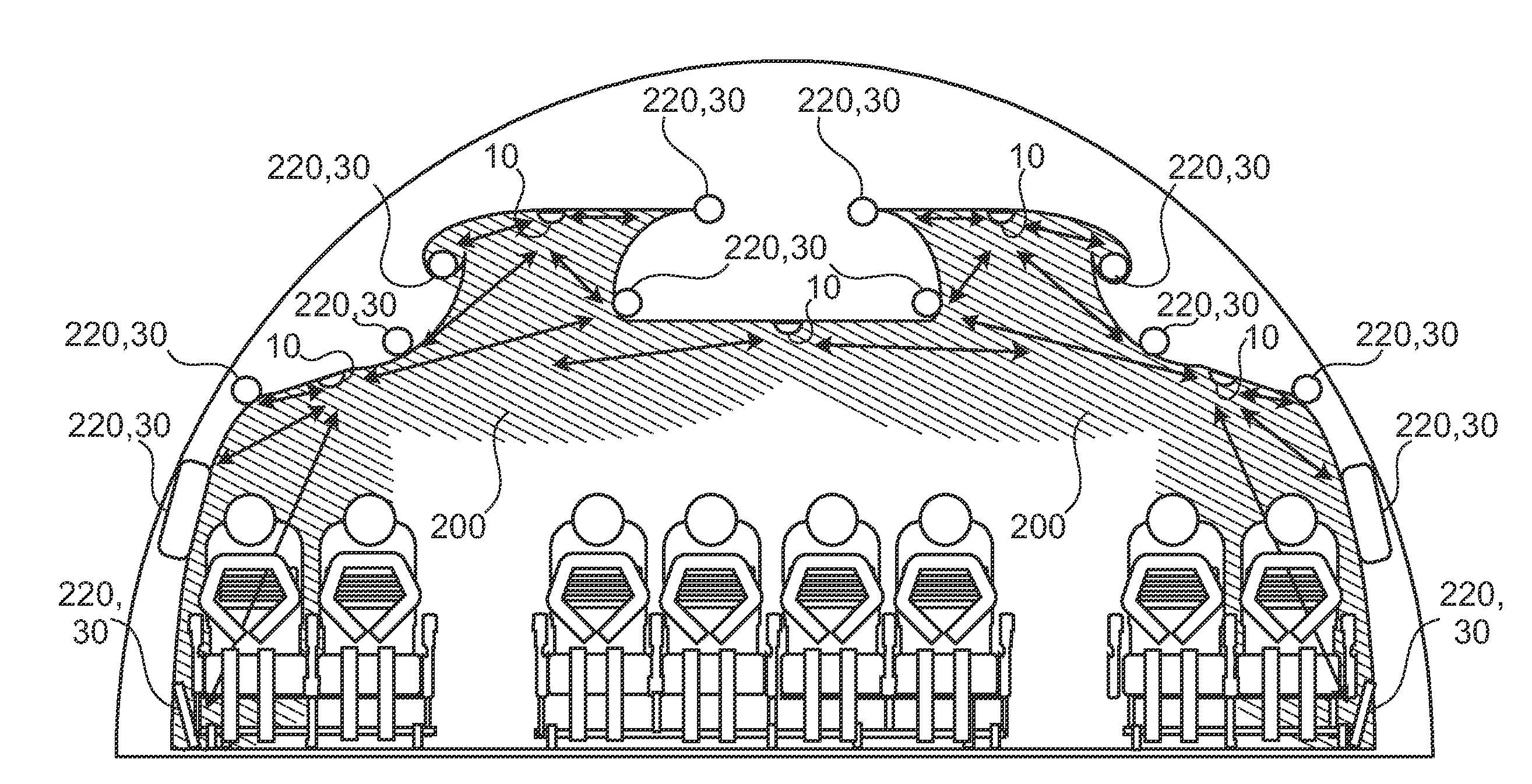
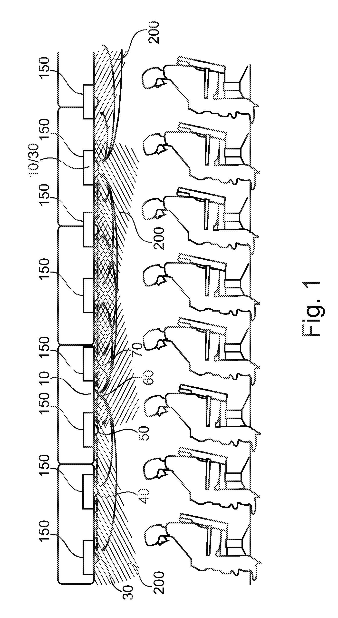
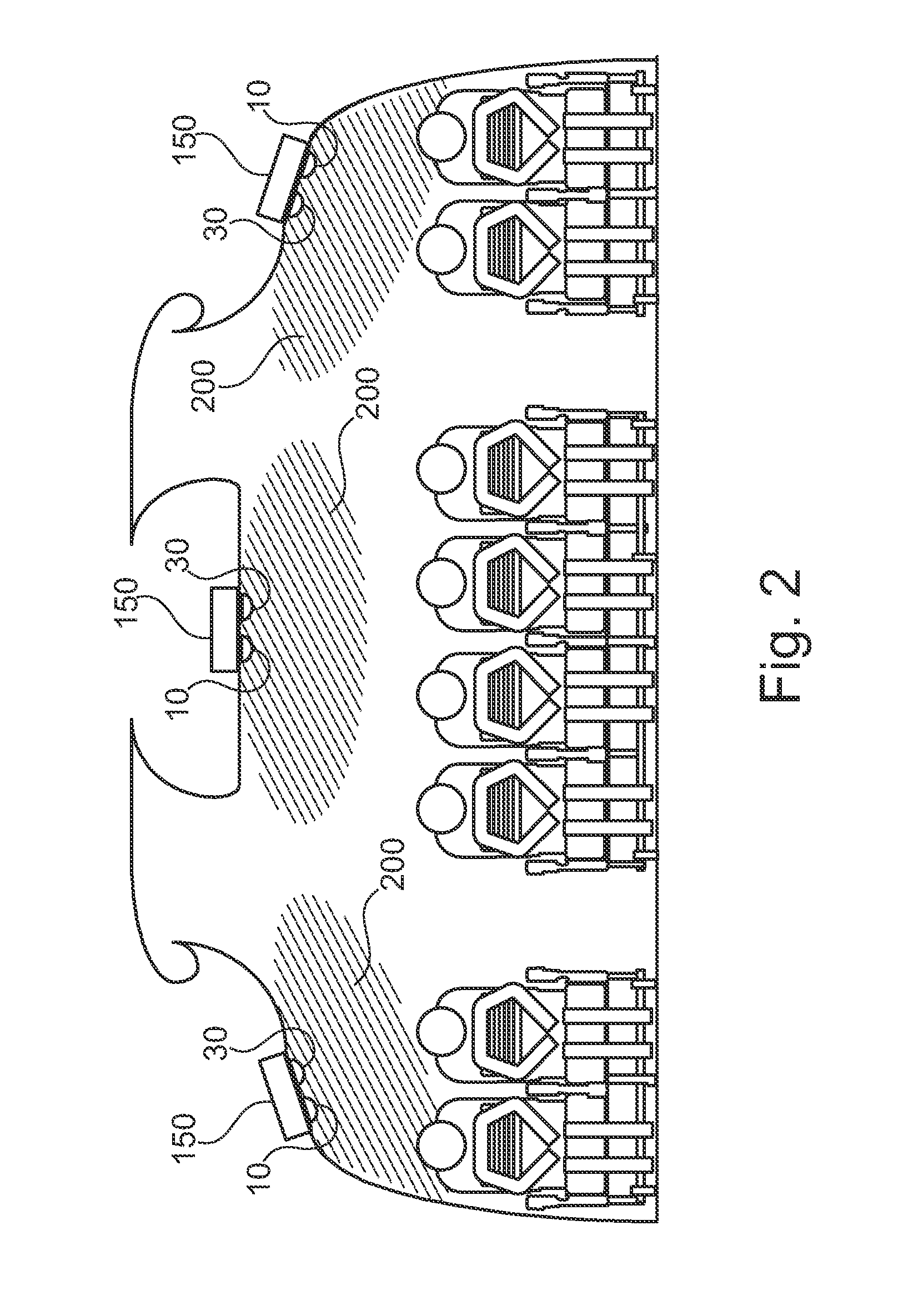
[0066]FIGS. 1 and 2 show a schematic representation of a side and front view illustrating the supply area for optical wireless data transmission between first sending unit and passenger service unit according to an embodiment of the invention.

[0067]FIG. 1 up to FIG. 3 illustrates the use case “control, monitor and broadcast PSU”. The command and monitor data of passenger service unit (PSU) 150 as well as broadcast information are transmitted optically and wireless between OAPs 10 and OT 30, 40, 50, 60, 70 within their supply area (optical cell). For that reason each PSU 150 is equipped with an OT 30, 40, 50, 60, 70.

[0068]2...


PUM


Abstract

The invention relates to an aircraft data communication system as well as an aircraft comprising such a data communication system, in particular a wireless optical communication system inside an aircraft cabin and outside for aircraft services. The aircraft data communication system comprises a first sending unit 10 comprising a first sender and a first modulator, and a first receiving unit comprising a first receiver and a first demodulator. The communication system is adapted for a signal transmission between the first sender and the first receiver, wherein the signal transmission between the first sending unit and the first receiving unit is effected by light, and wherein the first modulator is adapted for modulating an amplitude of the transmitted light.

Description

REFERENCE TO RELATED APPLICATIONS[0001]This application claims the benefit of the filing date of U.S. Provisional Patent Application No. 61 / 125,788 filed Apr. 29, 2008, the disclosure of which application is hereby incorporated herein by reference.FIELD OF INVENTION[0002]The invention relates to an aircraft data communication system as well as an aircraft comprising such a data communication system, in particular a wireless optical communication system inside an aircraft cabin and outside for aircraft services.TECHNOLOGICAL BACKGROUND[0003]Presently the data communication inside an aircraft cabin and for outside aircraft services is mainly based on wired signal guidance or on wireless radio frequency (RF) signal transmission. The wired signal transmission is less flexible regarding aircraft cabin (re-) configuration, short time customer requests and lead-time with respect to additional weight, costs and design effort in comparison to an aircraft with standard equipment. The signal t...

Claims


Application Information

Patent Timeline
Patent Type & Authority Applications(United States)
IPC IPC(8): H04J14/00H04B10/00H04B10/118
CPCH04B10/1149
Inventor HAAS, HARALDBASSOW, ERHARDELGALA, HANYMESLEH, RAED
Owner AIRBUS OPERATIONS GMBH
Why Eureka
Try Eureka