Drive system

a technology of drive system and torque transmission, which is applied in the direction of gearing details, bearing unit rigid support, gearing, etc., can solve the problems of difficult assembly of partitions, difficult to achieve the desired transmission torque with lubricant oil, etc., and achieve reliable torque transmission without a large power loss, high efficiency, and quick and suitable output

a technology of drive system and torque transmission, which is applied in the direction of gearing details, bearing unit rigid support, gearing, etc., can solve the problems of difficult assembly of partitions, difficult to achieve the desired transmission torque with lubricant oil, etc., and achieve reliable torque transmission without a large power loss, high efficiency, and quick and suitable output

US20110070990A1Inactive Publication Date: 2011-03-24AISIN AW CO LTD

Image

  • Drive system
  • Drive system
  • Drive system

Examples


Embodiment Construction

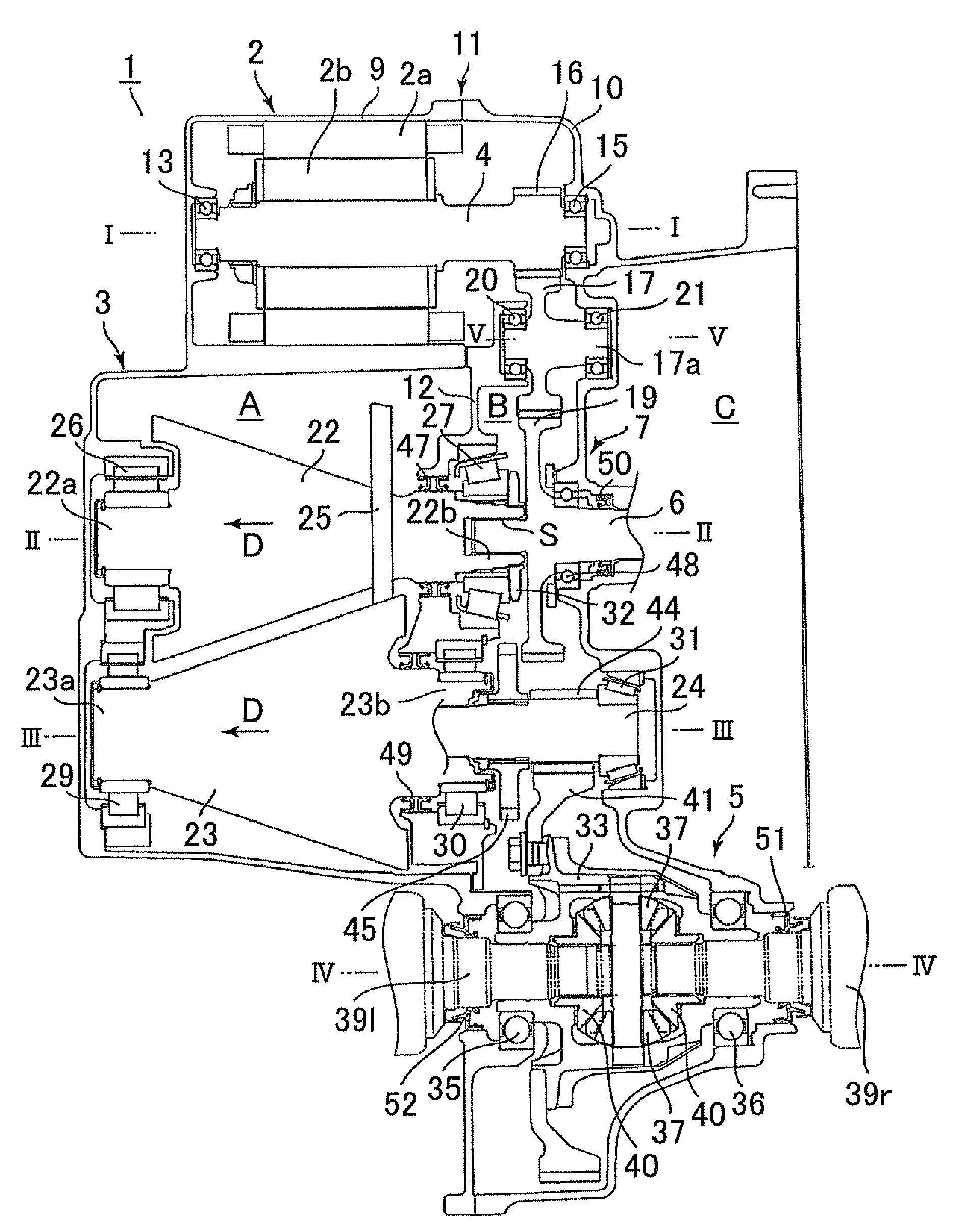
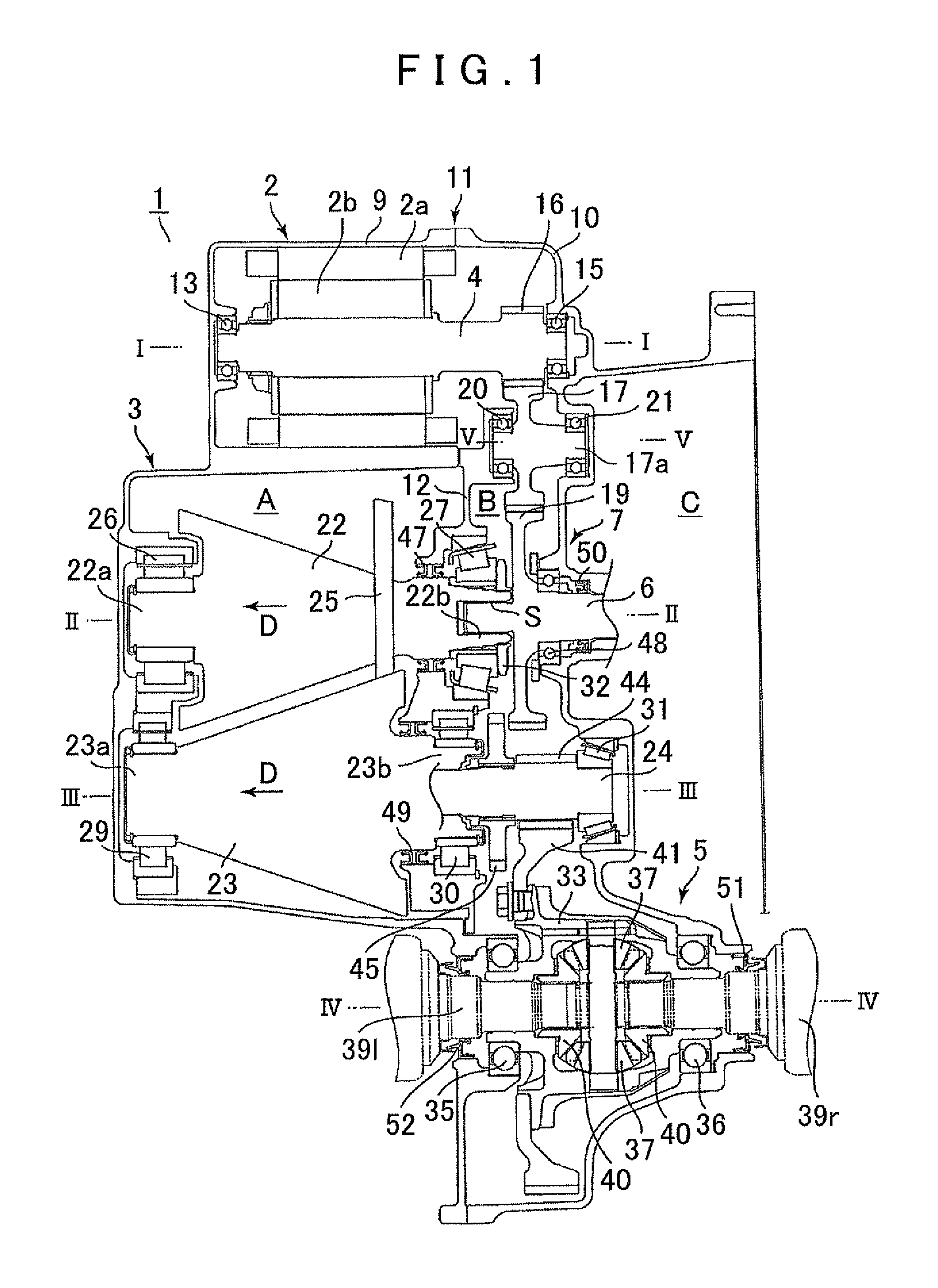
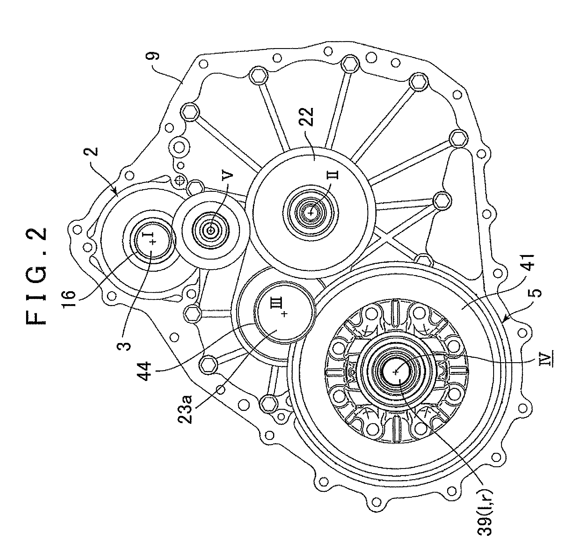
[0036]A hybrid drive system to which the present invention is applied will be described below with reference to the attached drawings. As shown in FIGS. 1 and 2, a hybrid drive system 1 includes an electric motor 2, a cone ring type continuously variable transmission device (a friction type continuously variable transmission device) 3, a differential device 5, an input shaft 6 that moves in accordance with an output shaft of an engine (not shown), and a gear transmission device 7. The above devices and shafts are housed in a case 11 that is formed by two case members, that is, a case member 9 and a case member 10. Further, the case 11 includes a first space A and a second space B divided by a partition 12 in an oil-tight manner.

[0037]The electric motor 2 includes a stator 2a fixed to the first case member 9, and a rotor 2b provided on an output shaft 4. A first end portion of the output shaft 4 is rotatably supported by the first case member 9 through a bearing 13, and a second end ...


PUM


Abstract

A drive system with a case divided into two oil-tight compartments. The first compartment is filled with traction oil and accommodates a friction type continuously variable transmission (CVT) device, and a second compartment filled with lubricant oil and a gear transmission device formed from a meshing rotary transmission mechanism. The CVT device includes an input member, an output member, and a ring interposed in such a way that the ring moves in an axial direction to steplessly change speeds. An input or output member of the CVT device includes a first axial portion rotatably supported by the case, and a second axial portion supported on a second side of the partition through a bearing that provides support in a thrust and radial direction. The bearing is mounted to the partition so that an inner race of the bearing is unrotatably connected to the second-side axial portion through a rotation stopper.

Description

INCORPORATION BY REFERENCE[0001]The disclosure of Japanese Patent Application Nos. 2009-274862 and 2009-218121 filed on Dec. 2, 2009 and Sep. 18, 2009, respectively, including the specification, drawings and abstract is incorporated herein by reference in their entirety.BACKGROUND OF THE INVENTION[0002]The present invention relates to a drive system that includes: a friction type, such as a cone ring type, continuously variable transmission device; and a gear transmission device formed from a meshing rotary transmission mechanism (such as a toothed gear, a chain, and a sprocket).DESCRIPTION OF THE RELATED ART[0003]A conventional drive system, such as a hybrid drive system, is known that integratedly incorporates a continuously variable transmission device and a gear transmission device. A belt type continuously variable transmission device is generally used as the continuously variable transmission device for the hybrid drive system. The belt type continuously variable transmission ...

Claims


Application Information

Patent Timeline
24 Mar 2011
Publication
US20110070990A1
IPC
F16H37/12; F16H57/04; F16C35/073; F16H15/22; F16H37/02; F16H57/021
CPC
B60K6/405; B60K6/48; B60K6/543; Y02T10/6221; F16H57/0453; F16H57/0454; F16H57/0491; F16H15/42
Inventors
YAMASHITA, MITSUGI; TAKAHASHI, SHOJI