
Inverted pendulum type moving body

a technology of moving body and pendulum, which is applied in the direction of vehicle position/course/altitude control, process and machine control, instruments, etc., can solve the problems of difficult us

Active Publication Date: 2011-03-24
HONDA MOTOR CO LTD
View PDF5 Cites 32 Cited by
  • Summary
  • Abstract
  • Description
  • Claims
  • Application Information

AI Technical Summary

Benefits of technology

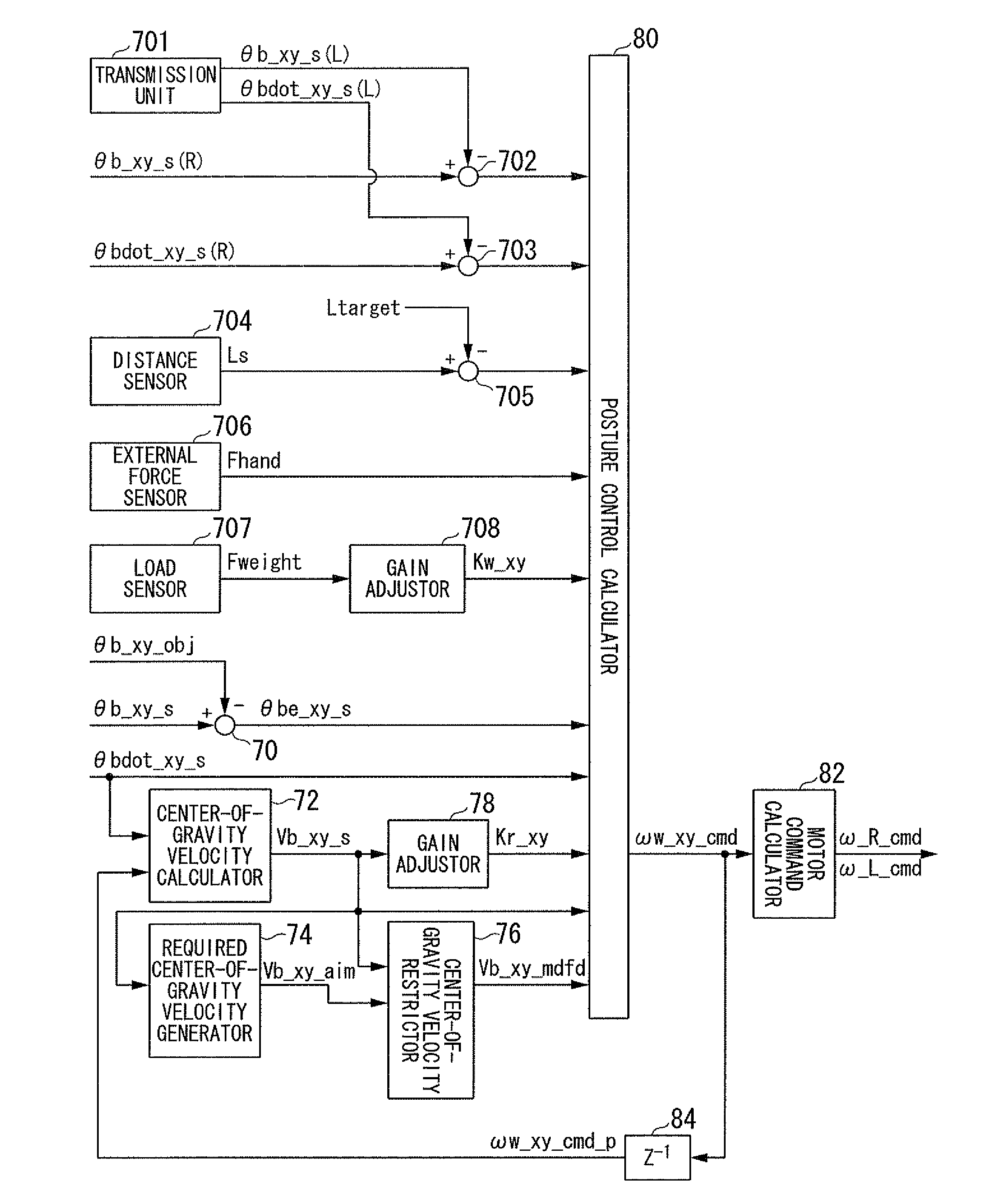
[0009]According to this configuration, the movement of the self moving body is controlled so that a state of the self moving body with respect to a current state of another moving body satisfies a predetermined condition. As a result, the self moving body may be moved in alignment with another moving body following a predetermined condition. Therefore, a plurality of inverted pendulum type moving body may be moved in alignment with each other.(2) In addition, the inverted pendulum type moving body may be configured as follows: the inverted pendulum type moving body further comprises an external force detection unit detecting an external force in a horizontal direction acting on a base body of the self moving body. Here, the movement control unit executes a feedback control of the self moving body so that the self moving body moves in a direction so as to reduce an external force detected by the external force detection unit.
[0010]According to this configuration, the self moving body is moved so as to reduce an external force detected by an external force detection unit. Therefore, it is possible to determine the direction in which the self moving body is moved according to the direction of the external force.(3) In addition, the inverted pendulum type moving body may be configured as follows: the inverted pendulum type moving body further comprises a load detection unit detecting a load in a perpendicular direction acting on a body of the self moving body. Here, the movement control unit reduces the gain coefficient of the feedback control with respect to an increase in a load detected by the load detection unit.
[0015]According to the inverted pendulum type moving body described in (2) above, the self moving body is moved so as to reduce an external force detected by an external force detection unit. Therefore, it is possible to determine the direction in which the self moving body is moved according to the direction of the external force.
[0016]According to the inverted pendulum type moving body described in (3) above, the gain of the feedback control is reduced in response to an increase in the load. Therefore, in a situation in which the load exists, it is possible to make the movement of the self moving body in a quiet manner.
[0019]According to the inverted pendulum type moving body described in (6) above, matching the tilt angle of the moving body is set as a predetermined condition. As a result, it is possible to maintain the self moving body and another moving body in a parallel manner. Thus, it is possible to match the postures of each moving body.
[0020]According to the inverted pendulum type moving body described in (7) above, a difference of the tilt angle of the self moving body being equal to a predetermined value is set to be a predetermined condition. Therefore, the state of the self moving vehicle and another moving vehicle may be maintained so that they are tilting in a direction different from one another.

Problems solved by technology

However, practically speaking, such use has been difficult.

Method used


Image

  • Inverted pendulum type moving body
  • Inverted pendulum type moving body
  • Inverted pendulum type moving body

Examples


Embodiment Construction

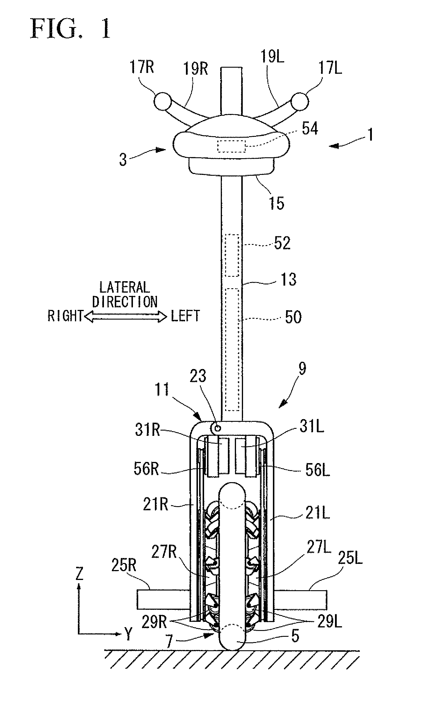
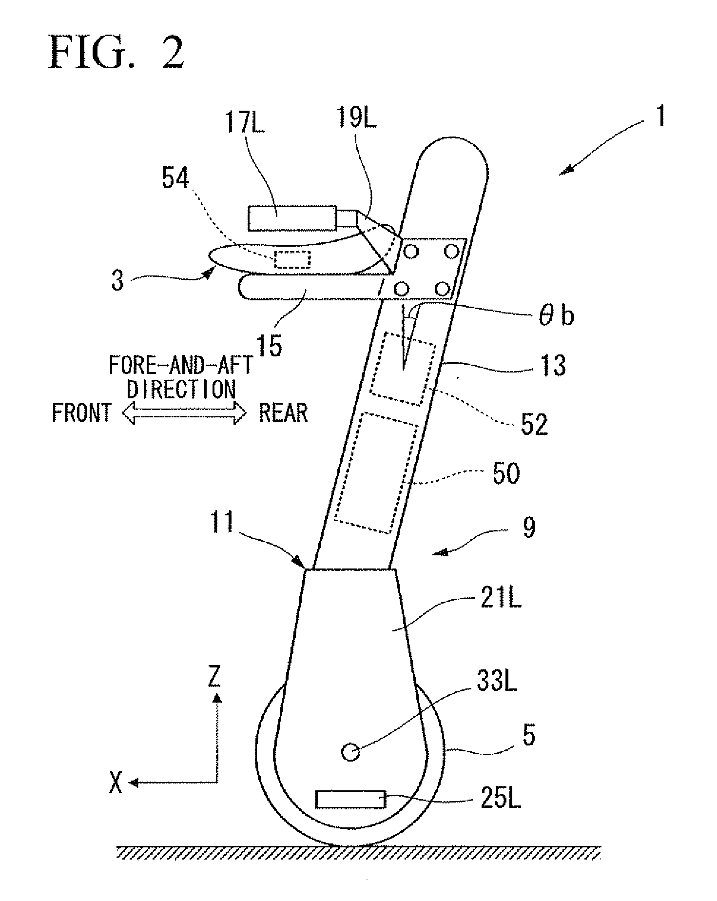
[0047]An inverted pendulum type moving body according to an embodiment of the present invention is based upon a technology relating to a movement control for an omnidirectional vehicle. The inverted pendulum type moving body according to the present embodiment further comprises, as characterizing components, a configuration for allowing a moving body to move in alignment with another moving body. In other words, the inverted pendulum type moving body according to the present embodiment comprises a configuration relating to a basic movement control for an omnidirectional vehicle, and also comprises a configuration for moving in alignment with another moving body.

[0048]Therefore, in the following description of the present embodiment, the section entitled “1. Technology On Which An Inverted Pendulum Type Moving Body Is Based (Omnidirectional Vehicle)” provides an explanation of a seating type omnidirectional vehicle, which pertains to technology on which a pendulum type moving body is...


PUM


Abstract

An inverted pendulum type moving body moving over a floor surface in a self standing manner, the inverted pendulum type moving body comprising: an information acquisition unit obtaining a state information indicating a current state of an another moving body; and a movement control unit controlling a movement of a self moving body, based on the state information, so that a state of the self moving body with respect to the current state of the another moving body satisfies a predetermined condition established so that the self moving body and the another moving body moves in alignment.

Description

[0001]The present application claims priority on Japanese Patent Application No. 2009-217925, filed Sep. 18, 2009, the content of which is incorporated herein by reference.BACKGROUND OF THE INVENTION[0002]1. Field of the Invention[0003]The present invention relates to an inverted pendulum type moving body, which can move in all directions (i.e., all directions in two dimensional space) on a floor surface. In particular, the present invention relates to an inverted pendulum type moving body which is movable in alignment with another moving body.[0004]2. Description of the Related Art[0005]An omnidirectional vehicle (an inverted pendulum type moving body) which can move in all directions (i.e., all directions in two dimensional space) on a floor surface has been suggested by the applicant, for example, in PCT International Publication No. WO 08 / 132,778 (hereinafter referred to as “Patent Document 1”) and in PCT International Publication No. WO 08 / 132,779 (hereinafter referred to as “P...

Claims


Application Information

Patent Timeline
Patent Type & Authority Applications(United States)
IPC IPC(8): G06F19/00
CPCB60L15/10B60L2200/16Y02T90/16B62K3/007Y02T10/7258B62K1/00B62K11/007Y02T10/64Y02T10/72
Inventor TAKENAKA, TORUKOBASHI, SHINICHIROKOYAMA, TAIJIIZUMI, HIDEHARUKUWABARA, KAZUYA
Owner HONDA MOTOR CO LTD
Learn More