Cyclic actuation system for a controllable pitch propeller and a method of providing aircraft control therewith

a technology of cyclic actuation and propeller, which is applied in the direction of rotors, marine propulsion, vessel construction, etc., can solve the problems of complex design of rotors and propellers, and the complexity of the articulated rotor system of helicopters, and achieve the effect of avoiding the complexity inheren

Active Publication Date: 2005-04-14
HAMILTON SUNDSTRAND CORP
View PDF18 Cites 14 Cited by
  • Summary
  • Abstract
  • Description
  • Claims
  • Application Information

AI Technical Summary

Benefits of technology

[0011] Accordingly, the present invention provides a propeller control system which generates cyclic pi

Problems solved by technology

Design of rotors and propellers is often quite complex.
As compared to rigid turboprop pro

Method used


Image

  • Cyclic actuation system for a controllable pitch propeller and a method of providing aircraft control therewith
  • Cyclic actuation system for a controllable pitch propeller and a method of providing aircraft control therewith
  • Cyclic actuation system for a controllable pitch propeller and a method of providing aircraft control therewith

Examples


Embodiment Construction

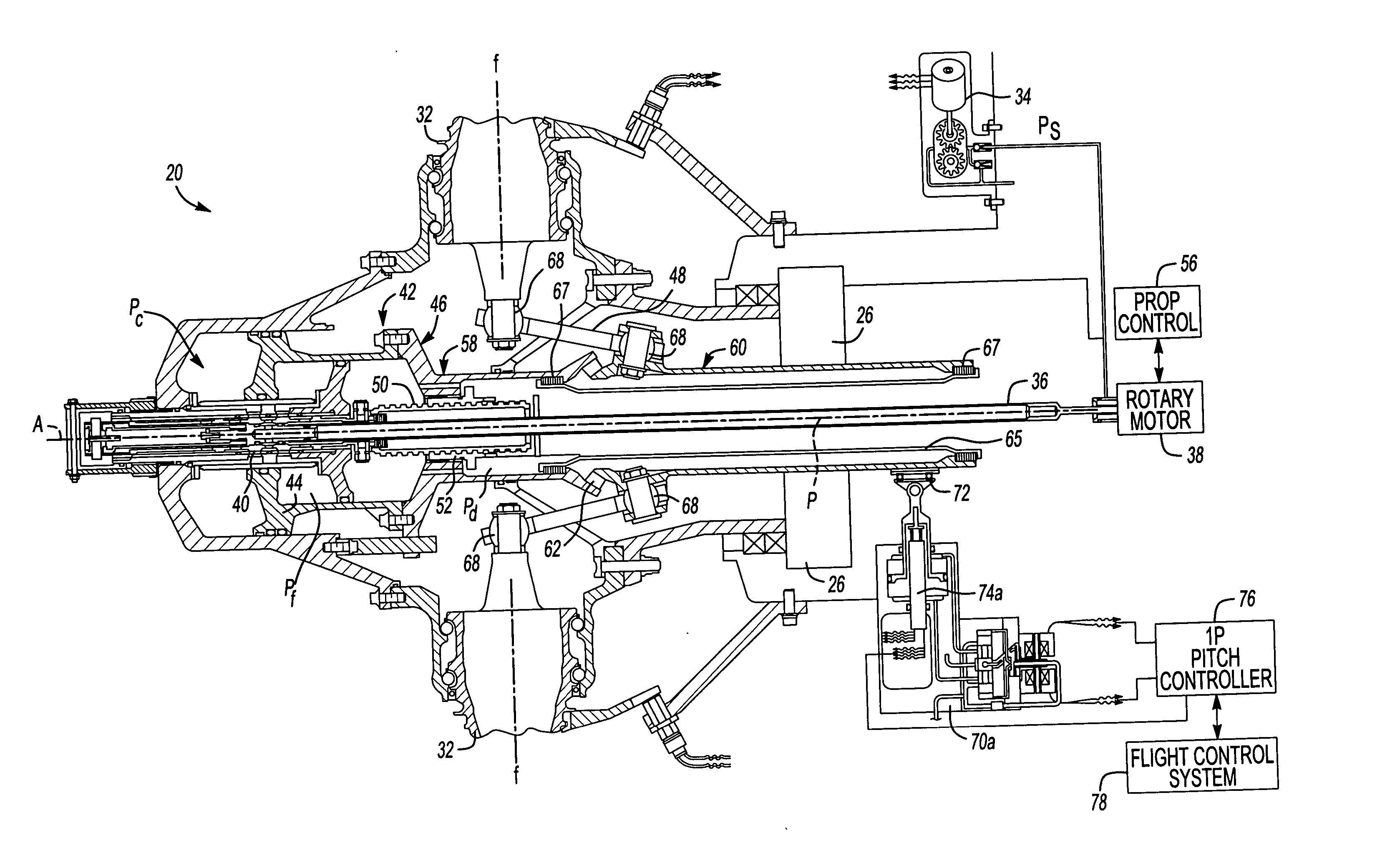
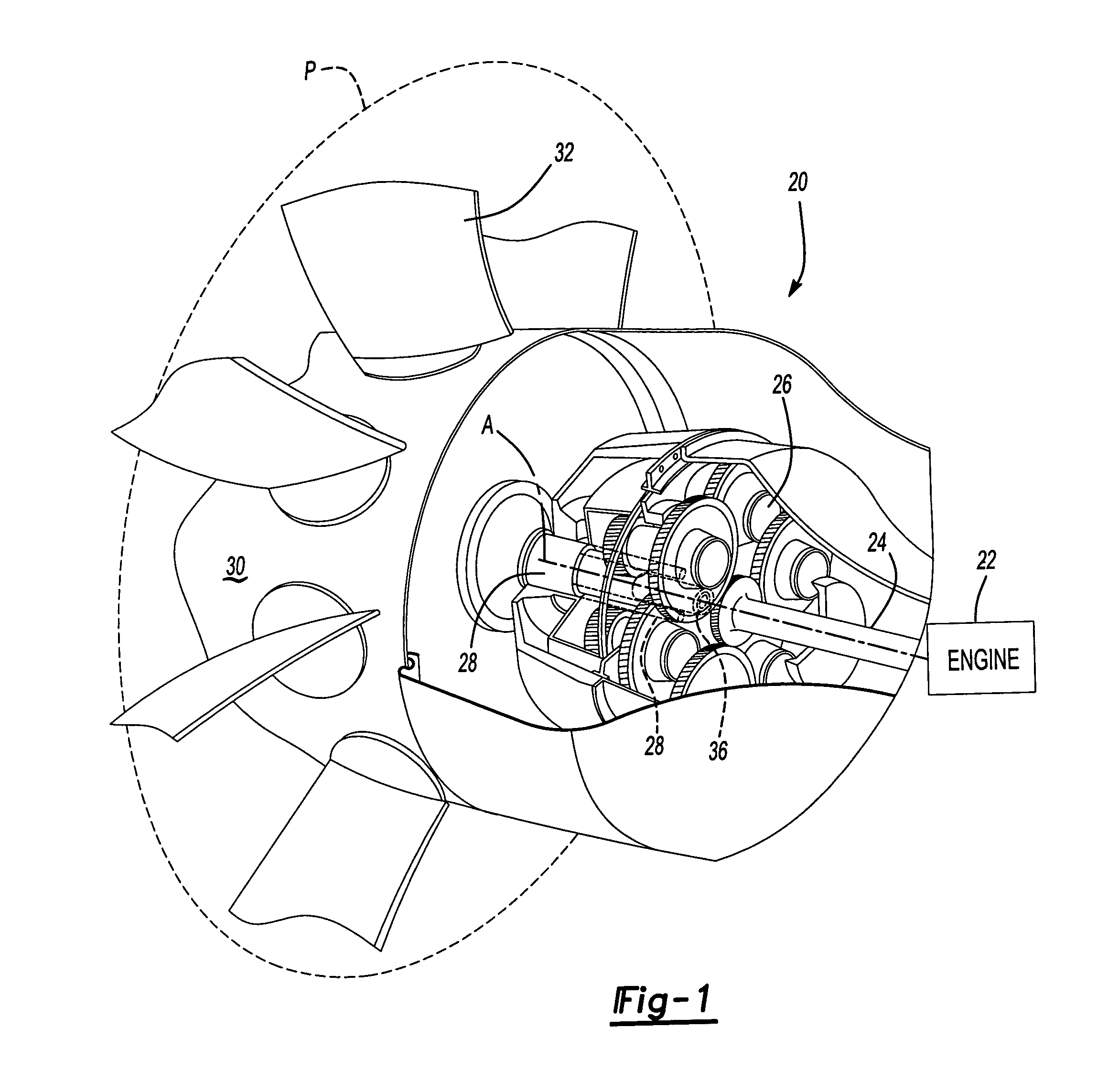
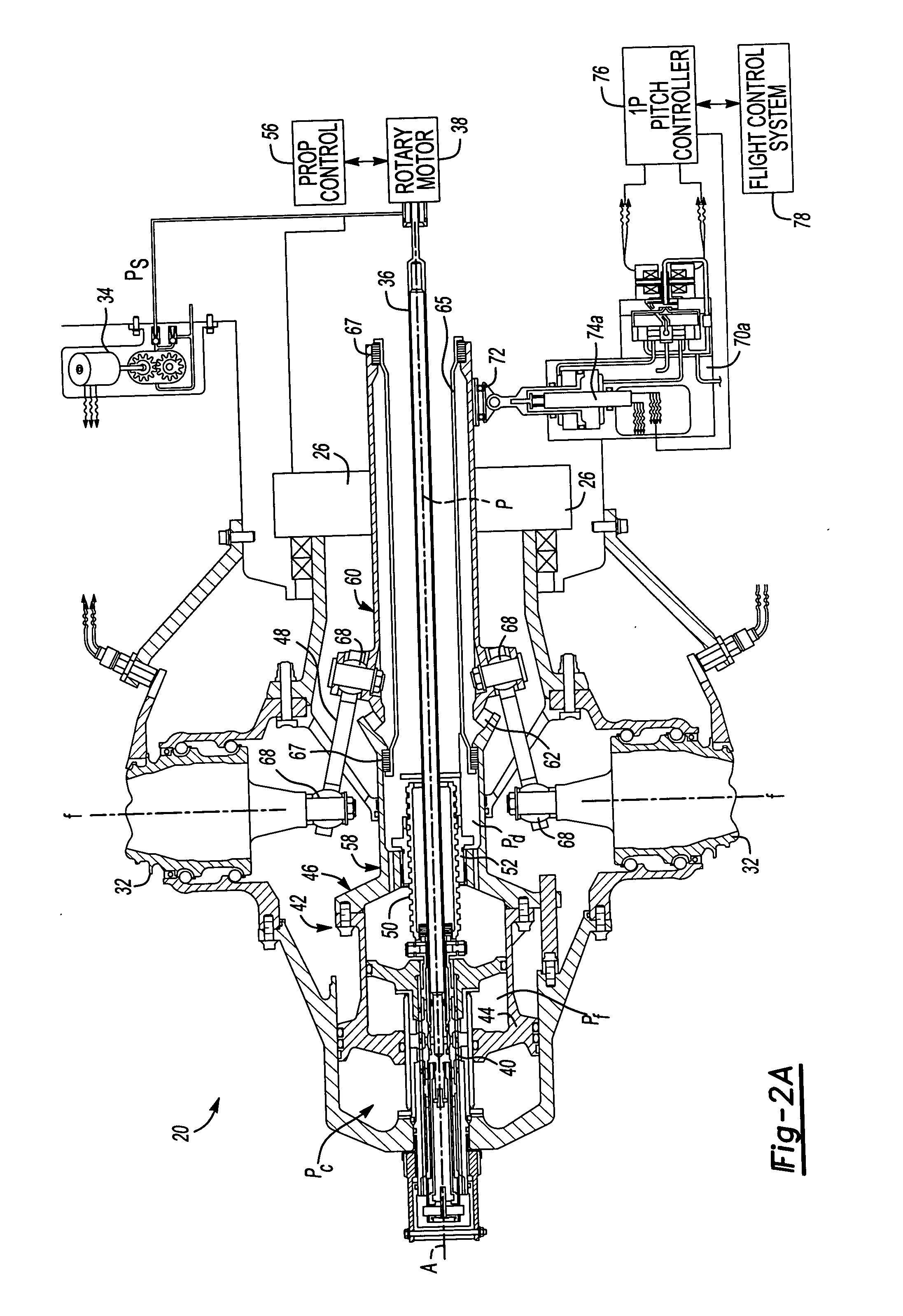
[0023]FIG. 1 illustrates a general perspective view of a propeller system 20. It should be understood that although a propeller system typical of a turboprop aircraft is illustrated in the disclosed embodiment, various rigid prop / rotor systems including tilt rotor and tilt wing systems will benefit from the present invention.

[0024] A gas turbine engine (illustrated schematically at 22) which rotates a turbine output shaft 24 at a high speed powers the propeller system 20. The turbine output shaft 24 drives a gear reduction gearbox (illustrated somewhat schematically at 26) which decrease shaft rotation speed and increase output torque. The gearbox 26 drives a propeller shaft 28 which rotates a propeller hub 30 and a plurality of propeller blades 32 which extend therefrom.

[0025] It should be understood that a conventional offset gearbox will also benefit from the present invention. Axis A is substantially perpendicular to a plane P which is defined by the propeller blades 32. It sh...


PUM


Abstract

A propeller control generates a once per revolution (1P) blade thrust variation through cyclic pitch of rigidly mounted non-flapping propeller blades. The resultant shaft bending moment is used to provide aircraft attitude control. Axial translation of a pitch change assembly including a pitch change yoke along an axis of rotation drives a pitch link attached to each propeller blade to collectively change the propeller blade pitch angle. The pitch change yoke includes a translating pitch change yoke portion and an articulatable pitch change yoke portion. Deflection of the articulatable pitch change yoke portion changes the pitch change effect of each pitch link as a function of its angular position such that a sinusoidal pitch angle is superimposed on normal pitch angle. Cyclic pitch change actuators deflect the articulatable pitch change yoke portion in any angular direction while the linear deflection of the cyclic pitch change actuators generate the magnitude of the cyclic pitch.

Description

BACKGROUND OF THE INVENTION [0001] The present invention relates to an aircraft control system, and more particularly to an actuation system for propeller blade angle control that provides cyclic pitch of individual propeller blades to generate a bending moment which is transmitted to the airframe to control an aircraft while minimizing external control surfaces. [0002] Design of rotors and propellers is often quite complex. A large number of factors must be taken into account, including flexure of the rotor under heavy loads and the required motions of the rotor blades with respect to the drive mechanism. [0003] Rigid turboprop propeller systems provide collective pitch control of the propeller blades. Pitch angles ranging from a fully feathered minimum drag angle to pitch angles which provide reverse thrust are typically provided to provide propeller speed and power management along a propeller axis of rotation. Inflow angles not along the axis of rotation due to aircraft maneuver...

Claims


Application Information

Patent Timeline
IPC IPC(8): B64C11/30B64C11/44
CPCB64C11/44B64C11/303B64C11/40B64C19/00B64C11/30B64C11/38B64C11/46
Inventor PERKINSON, ROBERT H.CARVALHO, PAUL A.AREL, DAVID V.
Owner HAMILTON SUNDSTRAND CORP
Why Eureka
Try Eureka