Failsafe system for raising and lowering at least one object

Inactive Publication Date: 2011-03-31
STONE PETER
View PDF8 Cites 6 Cited by
  • Summary
  • Abstract
  • Description
  • Claims
  • Application Information

AI Technical Summary

Benefits of technology

[0022]Other devices using the novel cam can be used in a multitude of devices where line control is important, such as on sailing yachts, raising and lowering objects such as potted plan

Problems solved by technology

The need for numerous working parts makes the cleat more costly to manufacture and more susceptible to failure.
Assembly of the cleat and its numerous parts contributes to the high cost of manufacture.
Because the cams typically have a thickness that approximates the diameter of the line being controlled such cleats tend to be large and bulky.
Also, the cams need to be molded or cast to provide the desired cam thicknesses and, thus, cannot be made of relatively thin sheet material.
Also, a serious problem is the damage that traditional cleats cause to the lines that are controlled.
Because the lines are locked in place when the relatively sharp teeth edges or ridges of the cams penetrate and deform the lines by applying substantial transverse forces that bite across the fibers or strands of the line, the sharp teeth frequently damage the strands or fibers forming the lines by and, with time, the teeth of the ca

Method used


Image

  • Failsafe system for raising and lowering at least one object
  • Failsafe system for raising and lowering at least one object
  • Failsafe system for raising and lowering at least one object

Examples


Embodiment Construction

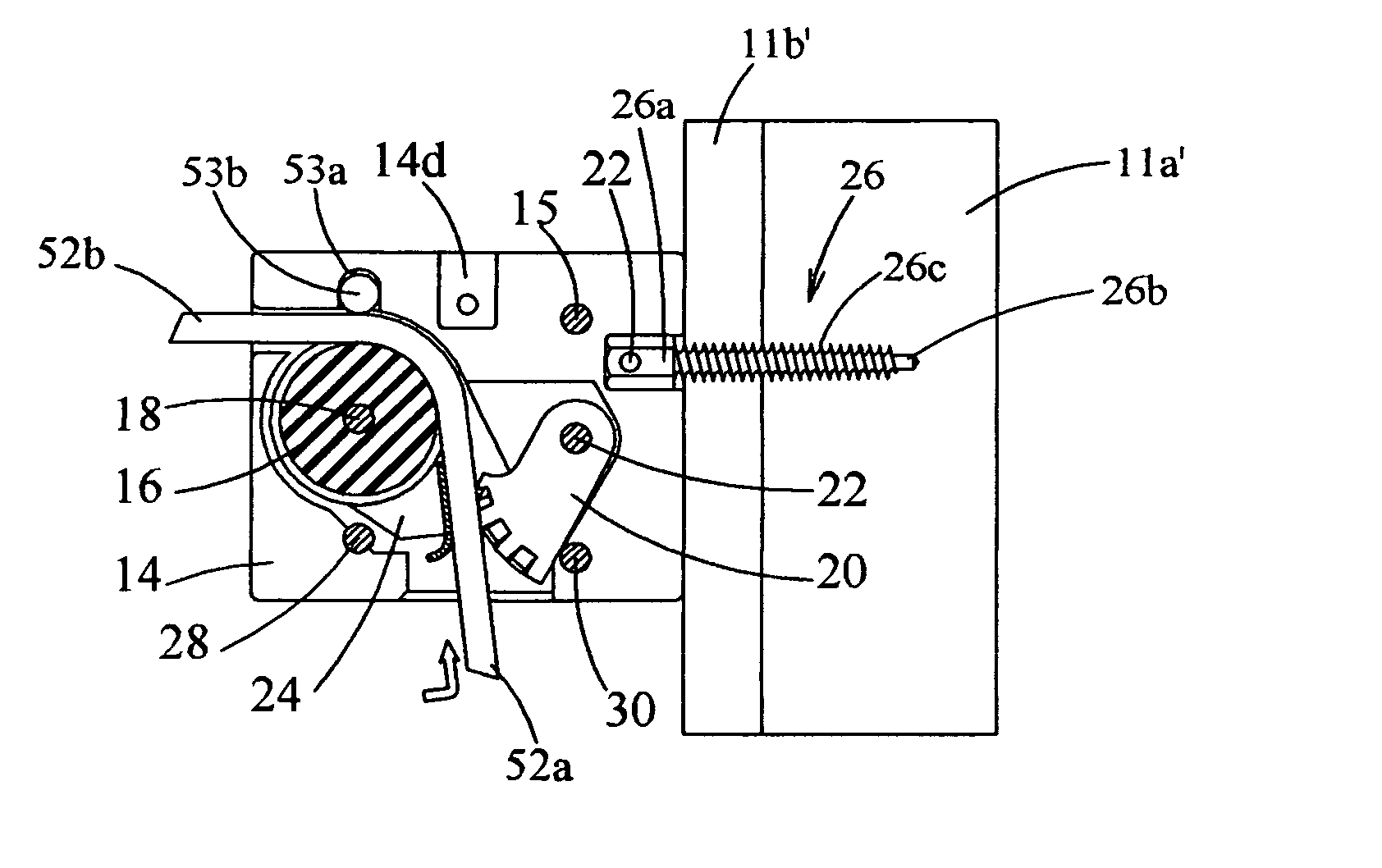
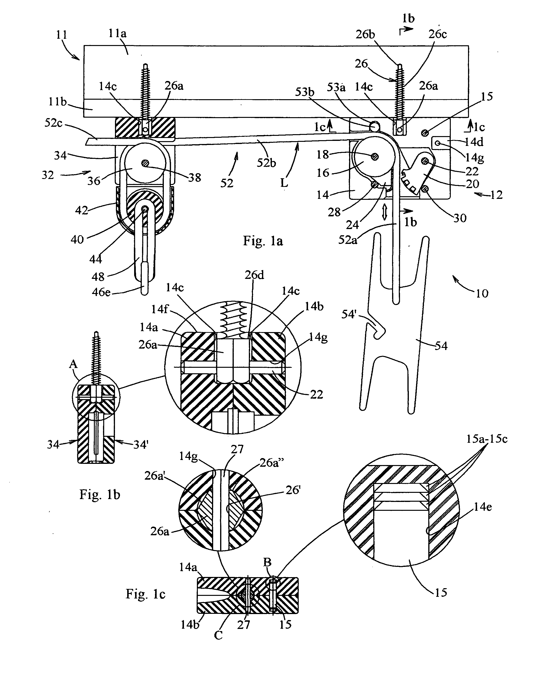
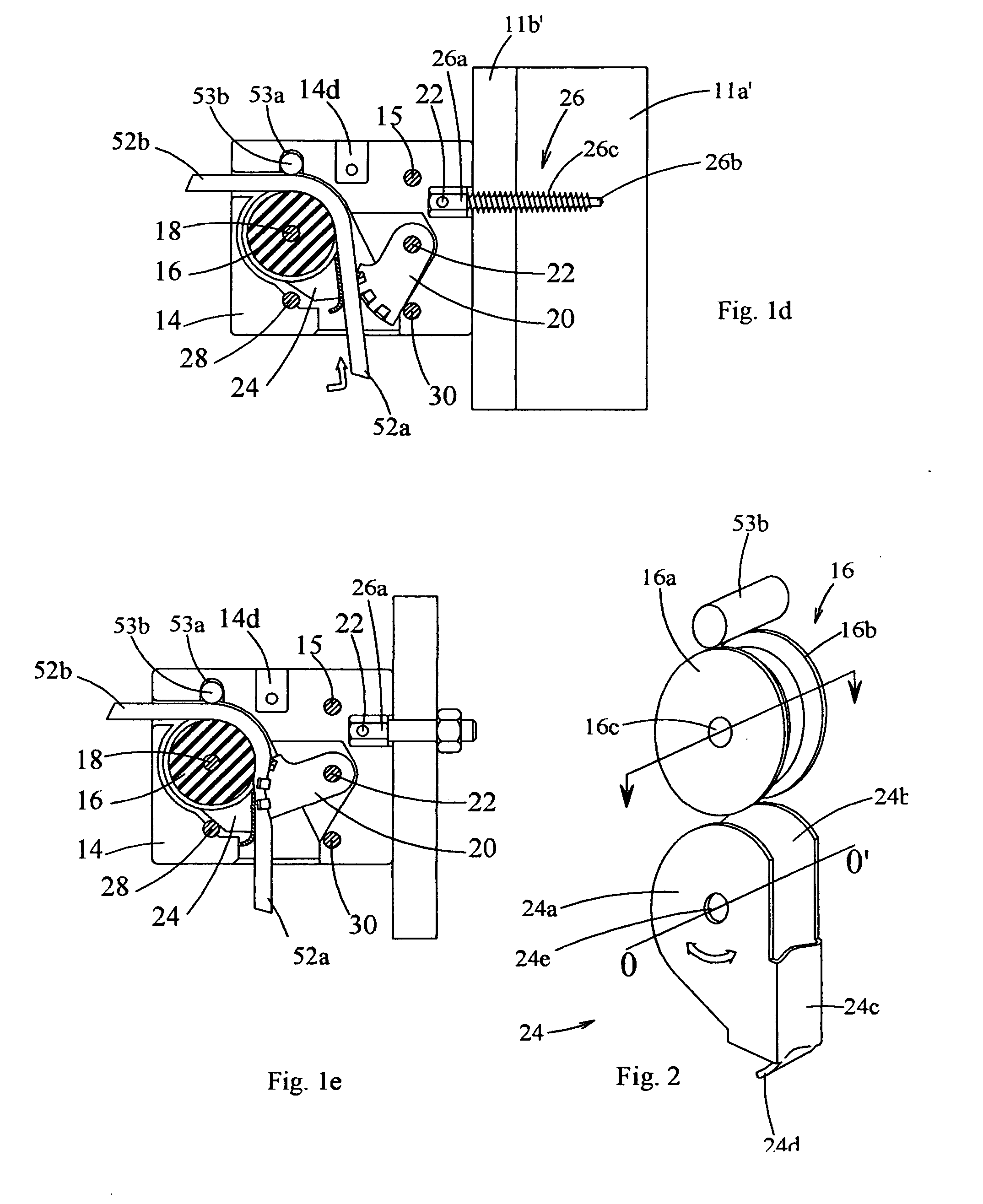
[0075]Referring now to the Figures, in which identical or similar parts are designated by the same reference numerals throughout, and first referring to FIGS. 1a-1c, a failsafe system for raising and / or lowering an object or a plurality of objects in accordance with the present invention, is generally designated by the reference numerals 10.

[0076]The cleated system of pulleys or sheaves 10 is configured to be conveniently mounted onto a ceiling 11 a by a consumer of average mechanical skills and with the simplest of tools, such as a screwdriver. The cleated system 10 includes a cleat 12 for locking / unlocking a control line L, as to be more fully described.

[0077]The cleat 12 includes a housing 14 that is shown to be generally rectangular in shape. However, as will become evident, the specific shape of the housing 14 is not critical and generally any rectangular or other configuration suitable for the purpose, such as a square configuration, can be used.

[0078]The housing 14 is formed ...


PUM


Abstract

A cleat with automatic line-locking, includes a frame having proximate and remote sides and formed with a passageway, extending between the proximate and remote sides, for receiving a line for movement along a first line moving direction from the proximate to the remote sides and an opposing line pulling direction from the remote to the proximate sides, and defining a line bearing surface or limit stop on one side of the passageway for limiting excessive transverse movements of the line in a direction to the one side of the passageway. Fasteners attach the frame to a support surface. A cam is provided on the frame on the other or opposite side of said passageway and has a line engaging portion normally spaced a predetermined distance from the line. The cam is movable between a line releasing position and a line locking position and is arranged to normally disengage from the line, engagement of the line by the cam to the line locking position while advancing the line in the first line moving direction creating a force couple that wedges the line between the line bearing surface or limit stop and the cam that tends to arrest or stop the line relative to the frame fixed on the support surface. The cam is formed of generally flat sheet material defining a cam plane and the line engaging portion being formed of a plurality of generally flat pressure-engaging segments or pressure pads that are angularly offset to opposite sides of said cam plane and together generally defining a line-receiving region having a generally uniform cross-section configured to frictionally engage the line in the line locking position. Auxiliary sheave assemblies may be used to provide automatic failsafe operation by means of the cleat when raising or lowering an object on a hook or loop. A pusher may be used to urge the line to move in the direction of the cam especially when the line is released.

Description

CROSS-REFERENCE TO RELATED APPLICATIONS[0001]This is a continuation application of International Application No. PCT / US2009 / 006474 with an international filing date of Dec. 7, 2009, currently pending, which claims priority of U.S. Provisional Patent Application No. 61 / 201,817 filed on Dec. 15, 2008 and U.S. Provisional Patent Application No. 61 / 276,923 filed on Sep. 18, 2009.BACKGROUND OF THE INVENTION[0002]1. Field of the Invention[0003]The invention generally relates to line control devices and, more specifically to a failsafe system raising and lowering at least one object.[0004]2. Description of the Prior Art[0005]One traditional or common device for securing a line from advancing relative to a reference point is a cam cleat that includes a support structure through which the line passes and one or two pivotally mounted cams within the structure that can move between a first position in which the cam(s) permits the line to move along a given direction and a second position in wh...

Claims


Application Information

Patent Timeline
IPC IPC(8): F16G11/10
CPCB66D1/54B66D5/32Y10T24/3944Y10T24/3942Y10T24/394
Inventor STONE, PETER
Owner STONE PETER
Why Eureka
Try Eureka