Butterfly Valve Flow Control Device

a flow control device and valve technology, applied in the direction of pipe elements, engine components, mechanical equipment, etc., can solve the problems of inability to utilize the diffuser in any other valve, noise, cavitation-induced damage in liquid service, etc., and achieve the effect of maximizing the effect of the control device and facilitating installation

Inactive Publication Date: 2011-03-31
YEARY & ASSOCS
View PDF26 Cites 26 Cited by
  • Summary
  • Abstract
  • Description
  • Claims
  • Application Information

AI Technical Summary

Benefits of technology

[0012]In an alternate embodiment, the flow control channels between each of the teeth can also include a sloped surface to restrict and limit the amount of fluid flowing through the control device. The configuration of each of the teeth and flow control channels formed in the control device can be selected to maximize the effect of the control device on the fluid flow through the valve assembly.
[0013]When the valve body

Problems solved by technology

One of the basic problems for butterfly valves is that the pressure drop tends to cause cavitation and consequent cavitation-induced damage in liquid service and noise in gas service.
Although this configuration functions well, it is not possible to utilize the diffuser in any other valve since the diffuser is directly incorporated into the valve vane.
In addition, this type of diffuser has little or no effect on the ability of the valve element to provide improved flow contro

Method used


Image

  • Butterfly Valve Flow Control Device
  • Butterfly Valve Flow Control Device
  • Butterfly Valve Flow Control Device

Examples


Embodiment Construction

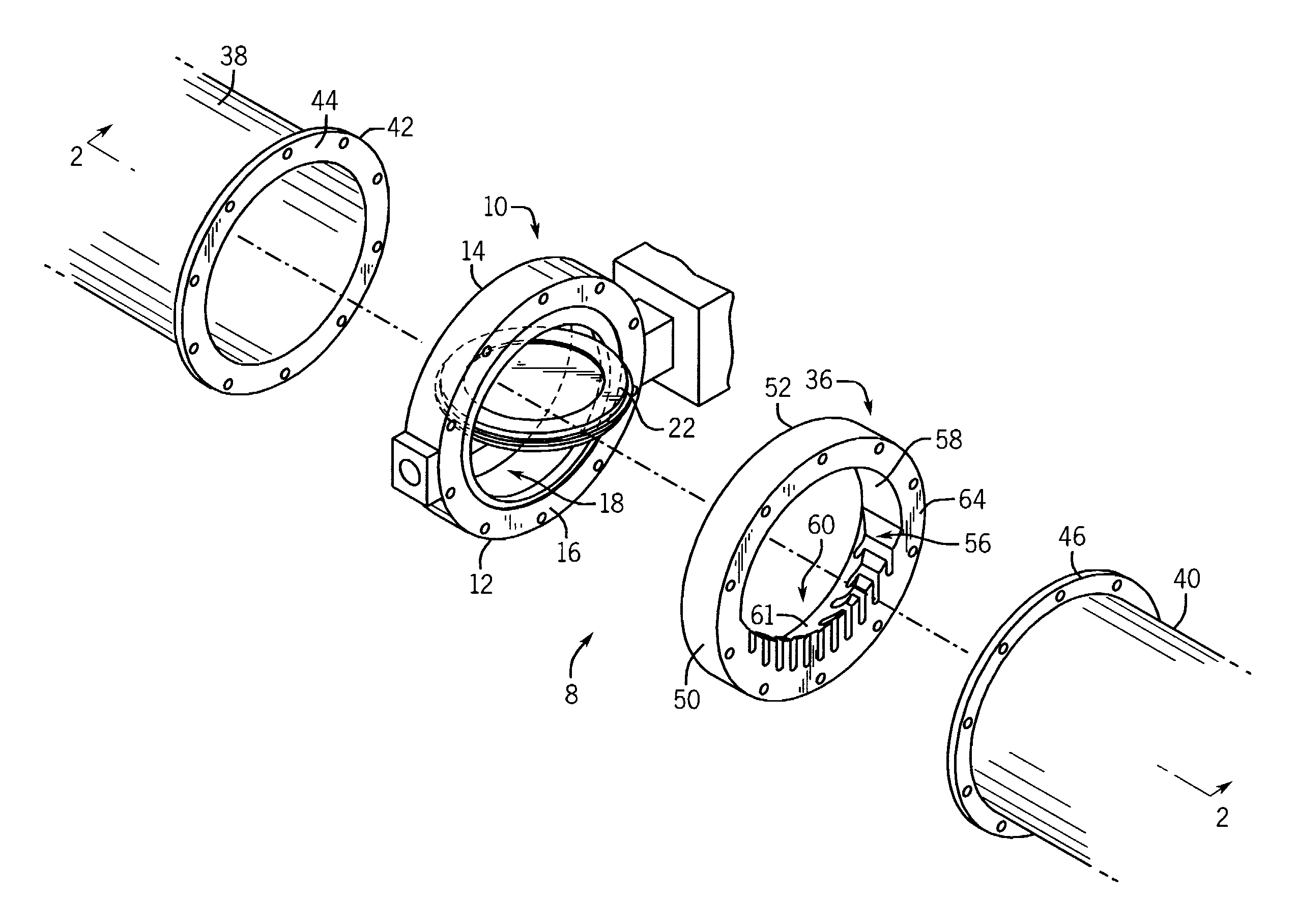
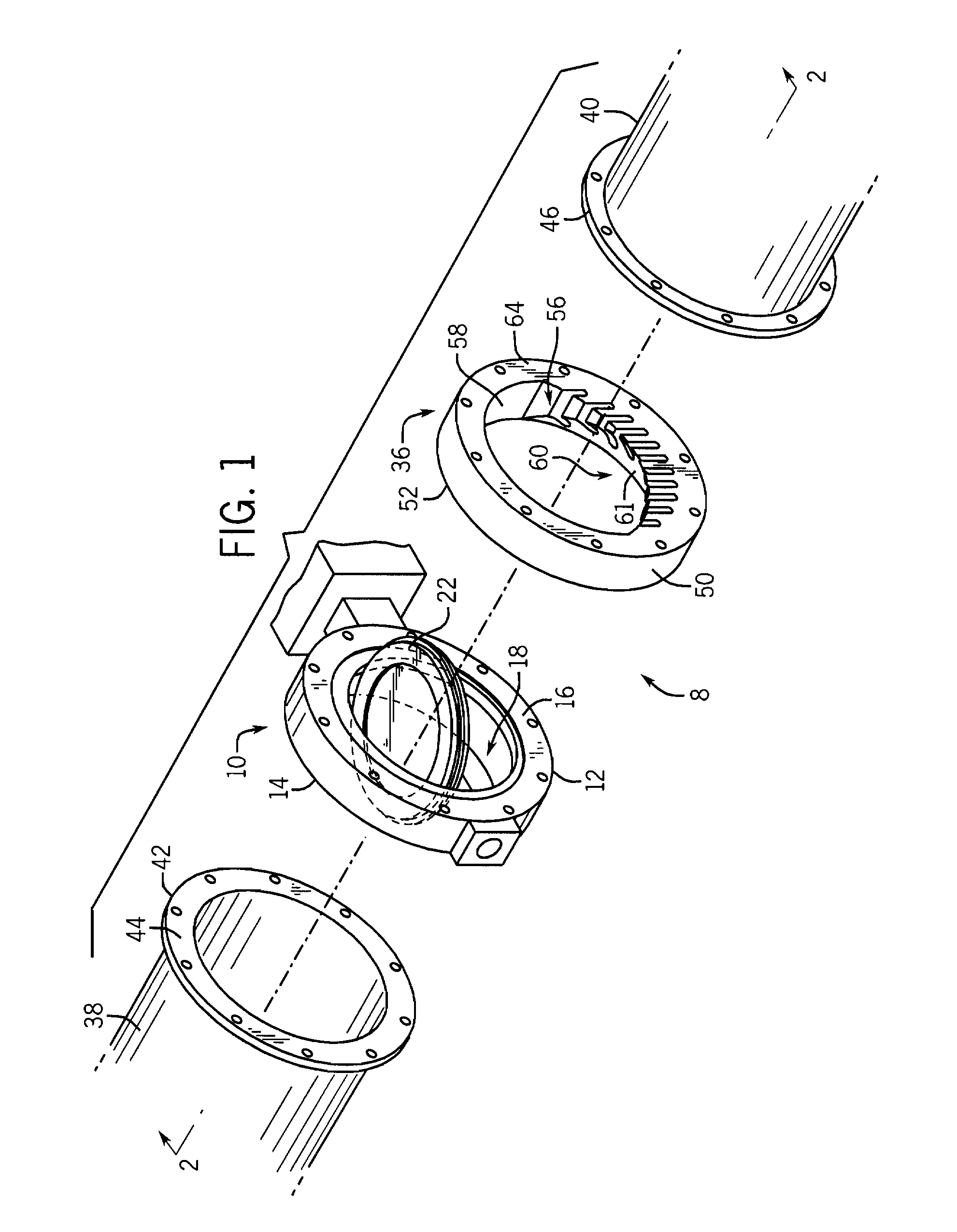
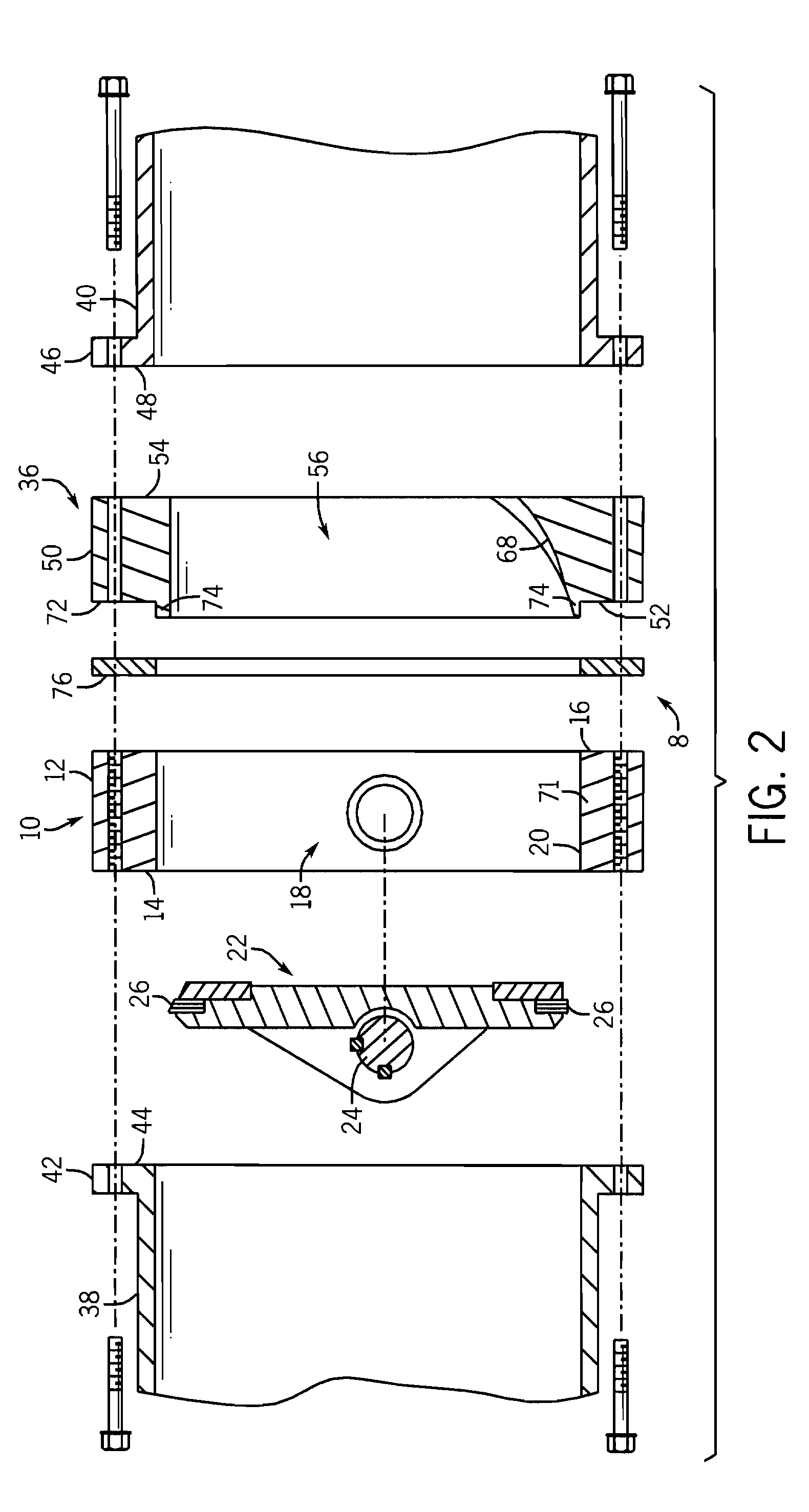
[0026]FIG. 1 illustrates a control valve assembly 8 that includes a control system that modifies the control characteristics of a conventional butterfly valve 10 such that the butterfly valve 10, with the control system installed, more closely approximates the flow characteristics of a globe valve. As shown in FIGS. 1 and 2, the butterfly valve 10 includes a valve body 12 that extends from a planar upstream face surface 14 to a downstream face surface 16 and is preferably formed from a metallic material, such as stainless steel. The valve body 12 defines an open passage 18 that allows fluid to flow through the valve body 12 from the upstream face surface 14 to the downstream face surface 16. The open passage 18 is defined by a generally cylindrical inner wall 20.

[0027]The butterfly valve 10 includes a valve disk 22 that is rotatably positioned within the open passage 18 by a pivot shaft 24. The pivot shaft 24 defines a shaft axis about which the valve disk 22 is rotatable between th...


PUM


Abstract

A control valve assembly that utilizes a butterfly valve having a valve body and a valve disk movable between a closed position and an open position. The control valve assembly includes a flow control device positioned downstream from the butterfly valve. The flow control device includes a series of teeth spaced by a series of flow control channels such that as the valve disk moves from the seated position to the fully open position, the outer sealing edge of the valve disk passes over the series of teeth to gradually expose the flow control channels. The control device aids in reducing cavitation, offers reduced dynamic torque and allows the control valve assembly to be inserted between an inflow pipe and an outflow pipe.

Description

CROSS-REFERENCE TO RELATED APPLICATION[0001]The present application is based on and claims priority to U.S. Provisional Patent Application Ser. No. 61 / 104,312, filed Oct. 10, 2008.BACKGROUND OF THE INVENTION[0002]The present disclosure generally relates to a device to control the flow of a fluid through a butterfly valve. More specifically, the present disclosure relates to a flow control device that can be utilized with a butterfly valve to provide enhanced control of the flow characteristics of the butterfly valve.[0003]Butterfly valves are in common usage for controlling the flow of various fluids, i.e. liquid or gas streams. Butterfly valves are used to throttle fluid flow and for on / off applications. A typical control valve assembly includes a body having a passage extending through it and a butterfly valve vane pivotally mounted within the body. The butterfly vane is characteristically in the form of a disk.[0004]When fluid passes through a partially open butterfly valve, the ...

Claims


Application Information

Patent Timeline
IPC IPC(8): F16L55/027F16K1/22
CPCF16K47/08F16K1/222
Inventor YEARY, ARTHUR R.BAUMAN, HANS D.
Owner YEARY & ASSOCS
Why Eureka
Try Eureka