Explosion Protection System for a High Pressure Lamp

a protection system and high-pressure lamp technology, which is applied in the direction of vacuum tube vessels/containers/shields, electric discharge lamps, incadescent envelopes/vessels, etc., can solve the problems of increased number of splintered objects, adversely affected by impinging vessel fragments, and explosion-like bursting of lamp vessels, etc., to achieve improved explosion protection and easy capture

Inactive Publication Date: 2011-03-31
OSRAM OPTO SEMICONDUCTORS GMBH & CO OHG
View PDF8 Cites 7 Cited by
  • Summary
  • Abstract
  • Description
  • Claims
  • Application Information

AI Technical Summary

Benefits of technology

[0008]The formation of the protective cap as a separate element also has the advantage that existing lamp arrangements are also equipped with such a side wall, with the result that already existing lamp arrangements can also be provided with improved explosion protection.
[0009]The contactless arrangement of the protective cap and the reflector also has the advantage that, in the event of the lamp bursting, which may occur, the reflector can absorb a large portion of the energy in the form of a breakage or a deformation without directly damaging the protective cap. The remaining energy or the reflector fragments can then easily be captured by the protective cap.
[0010]A risk to humans and machines as a result of lamp or reflector fragments is thus reduced in a direction remote from the reflector opening in the event of a lamp bursting. In order, in addition, to prevent lamp or reflector fragments from emerging in the direction of the light exit opening of the reflector and the protective cap, the reflector can additionally be covered by a transparent protective disk.
[0011]Particularly advantageous here is an exemplary embodiment in which the transparent protective disk has a first and a second disk element, the second disk element, which is arranged on the lamp side, being designed to capture a large proportion of the kinetic energy of lamp or reflector fragments in the event of a breakage. As a result of the breakage of the second disk element, so much kinetic energy can be converted that the remaining lamp fragments can be captured easily by the remaining first disk element.

Problems solved by technology

Nevertheless, owing to the extreme loads to which these lamps are subjected, material fatigue may arise, which can result in explosion-like bursting of the lamp vessel.
Owing to the high pressure prevailing in the lamp vessel, the energy released in the event of the lamp bursting is so high that the immediate vicinity is adversely affected by the impinging vessel fragments.
In the event of the lamp bursting, vessel fragments can even destroy the reflector, with the result that the number of splintered objects is increased.
In addition, the reflector fragments are much larger than the vessel fragments, with the result that the direct vicinity is endangered not only by the vessel fragments, but also by the large fragments of the reflector.
In this case, the direct vicinity can be a projection device or another machine, but it is also possible for humans to be at direct risk.
However, these protective measures have a few disadvantages.
Firstly, in the case of the metal grid, complete protection is not ensured since the base is not completely covered.
Secondly, in the case of the additional cap, said cap is connected fixedly to the reflector, which may result in a breakage of the reflector also causing a breakage of the protective cap.
In addition, in this case, the materials used need to have similar thermal properties since otherwise mechanical stresses may occur which damage the lamp.
However, this also means that sometimes only very unstable materials can be used, which do not make it possible to effectively prevent breakage of the reflector.

Method used


Image

  • Explosion Protection System for a High Pressure Lamp
  • Explosion Protection System for a High Pressure Lamp
  • Explosion Protection System for a High Pressure Lamp

Examples


Embodiment Construction

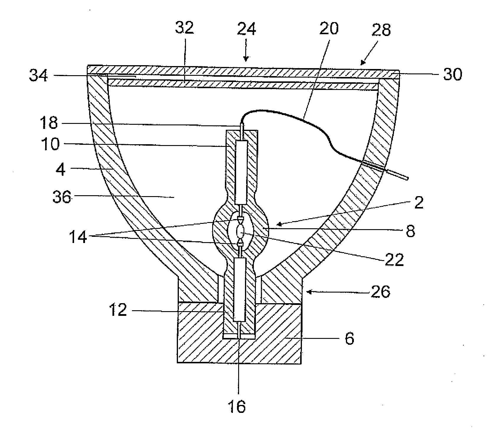
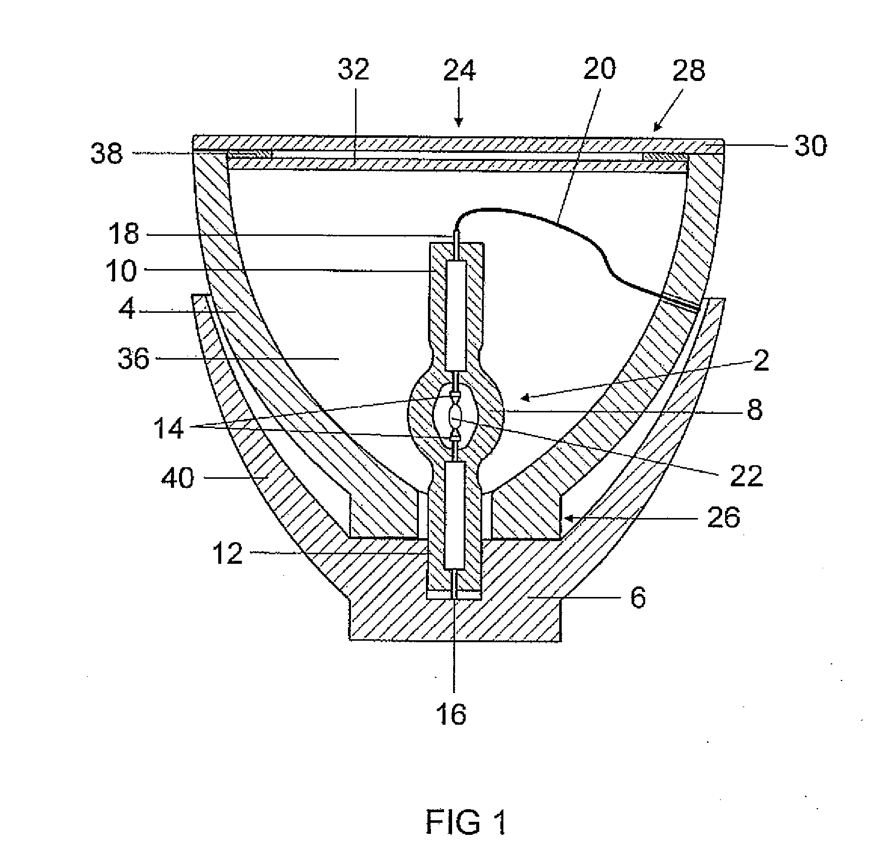
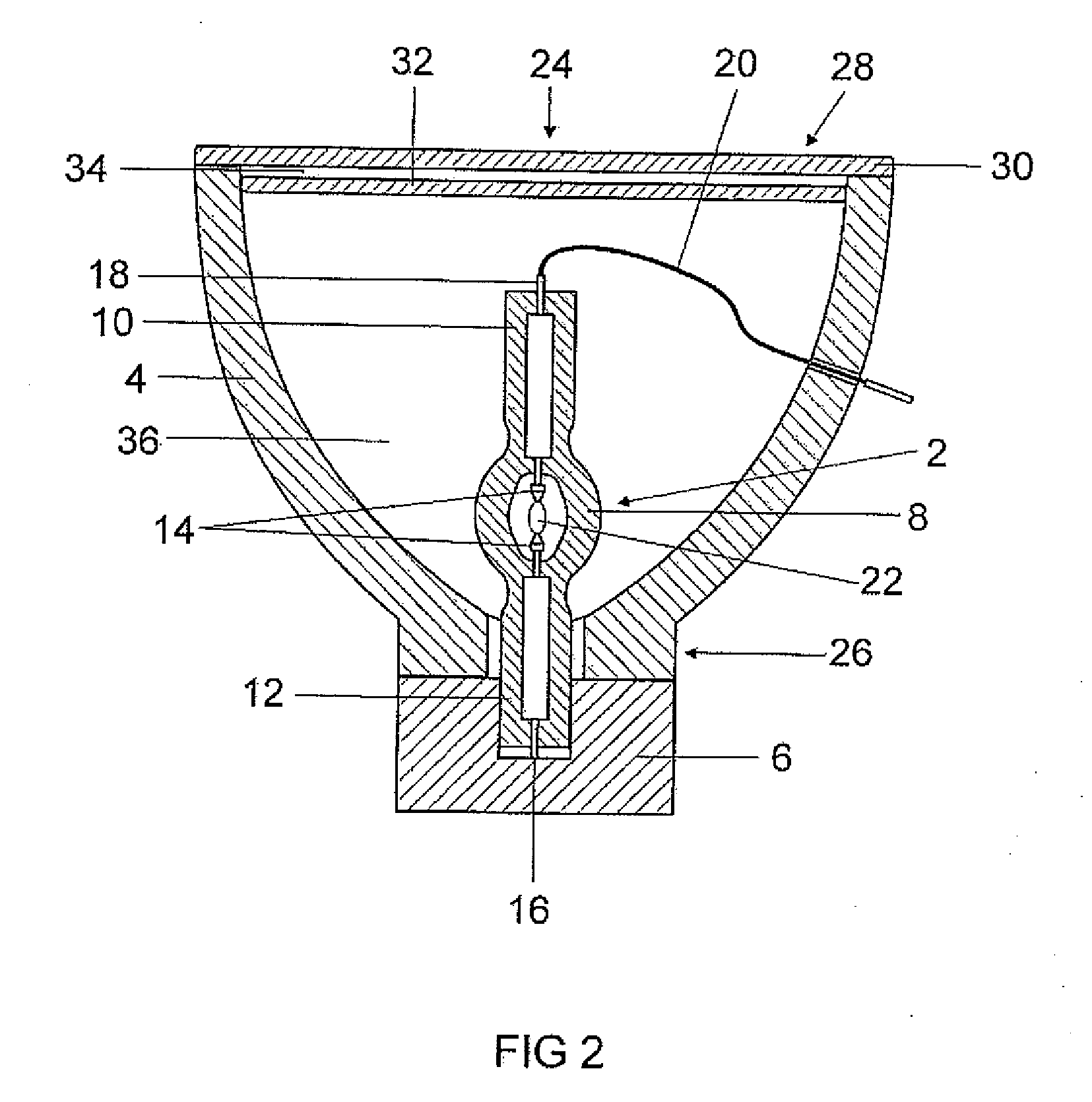
[0004]The object of the present invention is therefore to provide a high-pressure lamp which has improved protection in the event of bursting of the lamp vessel.

[0005]This object is achieved by virtue of the fact that a base for such a high-pressure lamp is formed with side walls, which surround the high-pressure lamp in the form of a protective cap.

[0006]Advantageously, the side walls in the form of a protective cap can be formed integrally with the base, but it is also possible for the side walls to be in the form of a separate protective cap element, which can be connected to the base. A connection to the base can in this case be performed by means of adhesive bonding, cementing, clamping, screwing or plugging, for example.

[0007]It is critical, both in the case of the integral formation and in the case of the connectable formation, that the side walls are connected to the base, but not to the reflector. Since there is therefore no direct contact between the reflector and the side...


PUM


Abstract

A base for a high pressure lamp, such base having lateral walls enclosing the lamp bulb. Also disclosed are lateral walls for a base, and a lamp system comprising such base.

Description

TECHNICAL FIELD[0001]The present invention relates to a base for a high-pressure lamp and to a lamp arrangement with such a base.PRIOR ART[0002]High-pressure lamps have a lamp vessel which is filled with a gaseous medium. In particular during operation, pressures of from typically a few bar to a few hundred bar arise within the lamp vessel. This relates inter alia to some halogen incandescent lamp types and in particular to high-pressure discharge lamps. The latter have, for example, a discharge bulb with an anode and cathode arranged therein, with an arc being produced between said anode and cathode during operation via a gas discharge. In addition, there are also high-pressure discharge lamps for AC operation, i.e. with two identical electrodes and an electrode-less discharge lamp, for example, with microwave excitation. In any case, the lamp vessel preferably consists of quartz glass or glass ceramic and is designed to withstand pressures of sometimes 300 bar or more. Nevertheles...

Claims


Application Information

Patent Timeline
Patent Type & Authority Applications(United States)
IPC IPC(8): H01K1/26H01J19/54
CPCH01J61/50H01J5/54
Inventor KROELL, JOSEF
Owner OSRAM OPTO SEMICONDUCTORS GMBH & CO OHG
Why Eureka
Try Eureka