Mitigation of transmitter passive and active intermodulation products in real and continuous time in the transmitter and co-located receiver

a passive and active intermodulation and transmitter technology, applied in the field of nonlinear transmitters and radio receivers, can solve problems such as unsatisfactory mitigation of the effect of the interference problem

Active Publication Date: 2011-03-31
FINESSE WIRELESS LLC
View PDF38 Cites 120 Cited by
  • Summary
  • Abstract
  • Description
  • Claims
  • Application Information

AI Technical Summary

Problems solved by technology

This is often only an approximation to linearity and the IMP issue is not totally mitigated.

Method used


Image

  • Mitigation of transmitter passive and active intermodulation products in real and continuous time in the transmitter and co-located receiver
  • Mitigation of transmitter passive and active intermodulation products in real and continuous time in the transmitter and co-located receiver
  • Mitigation of transmitter passive and active intermodulation products in real and continuous time in the transmitter and co-located receiver

Examples


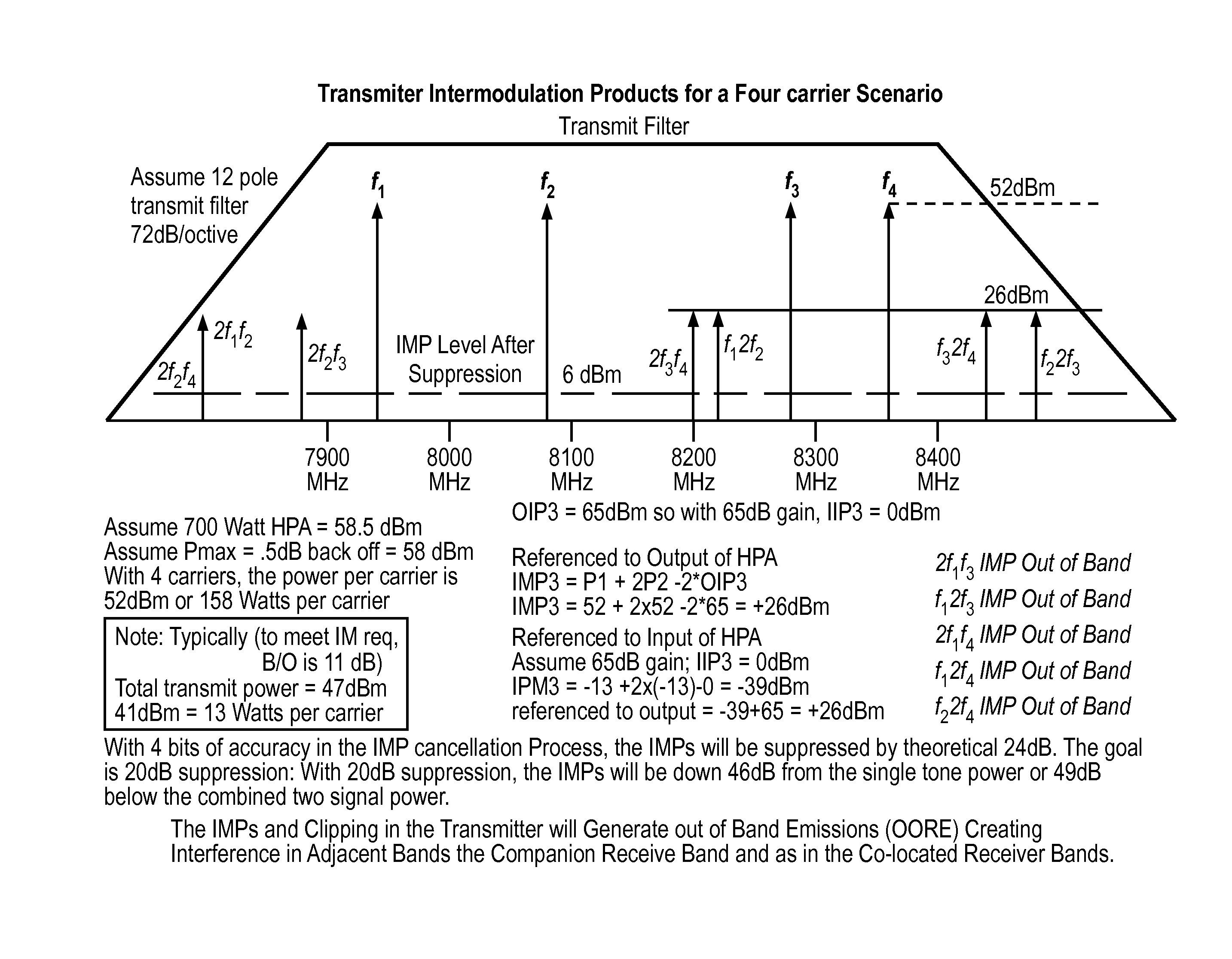
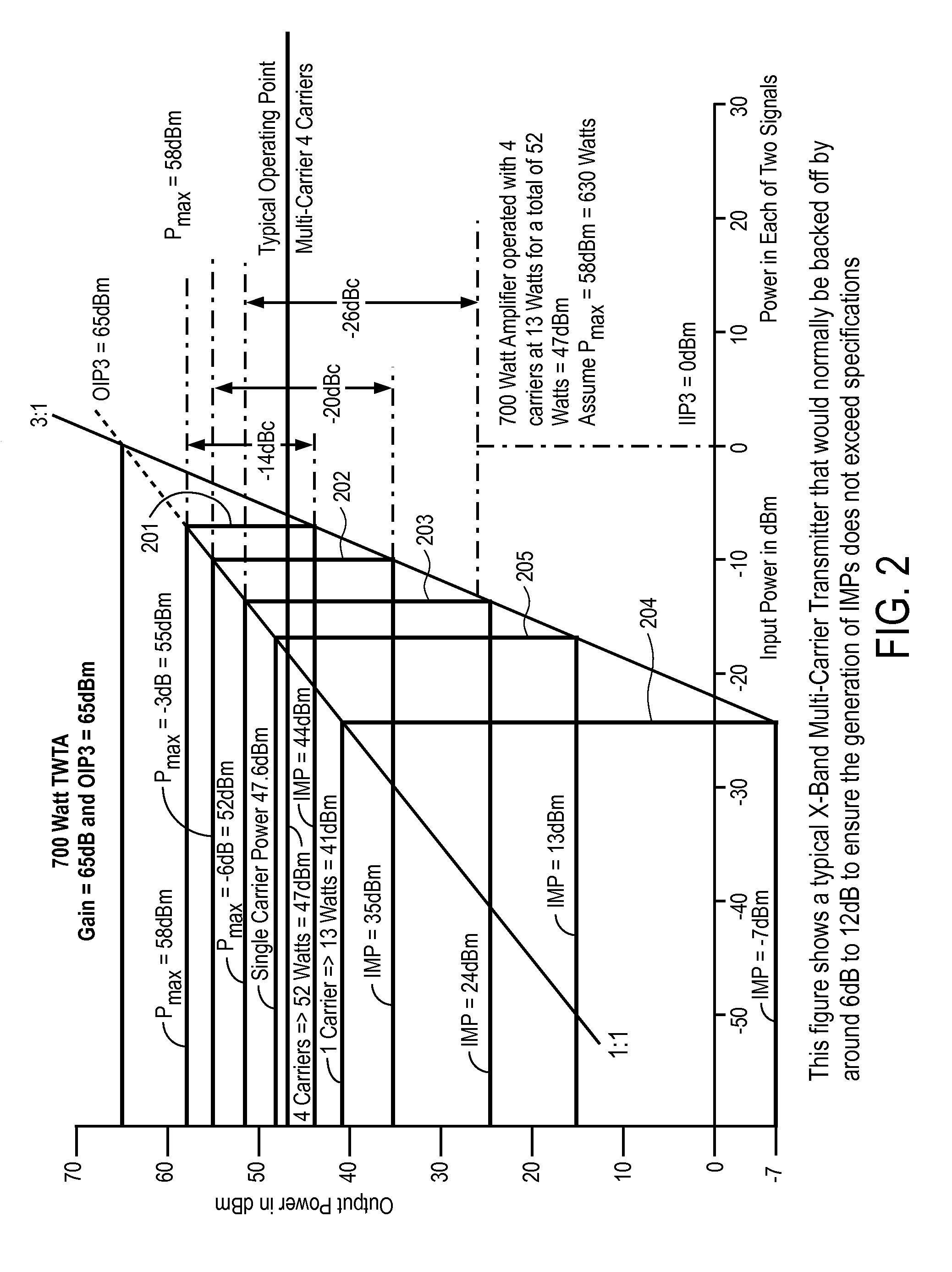
example imp scenario

[0134]For this example, the gain is assumed to be 65 dB and the OIP3 is 65 dBm so the IIP3 is 0 dBm.

[0135]In this example, we assume 4 carriers with an output power of 13 watts each for a total of 52 watts or 47 dBm from a maximum power output of 700 watts (58.5 dBm) and a Pmax of 58 dBm. (Note: This amplifier would most likely require phase coherent power combining of two or more TWTAs). In this case, the OSP1 and OSP2 would be at 13 watts or 41 dBm, or an input of −24 dBm (ISP). The output IMP would be:[0136]OIMP3=3(41)−2(65)=−7 dBm referenced to the HPA output

[0137]If referenced to the amplifier input,[0138]IIMP3=3(−24)−2(0)=−72 dBm=>−72 dBm+65 dB gain=−7 dBm=OIMP3:[0139]See FIG. 2, 204

Maximum Linear Power as Defined by MIL-STD-188 / 165A

[0140]If we ignore the multiple IMPs and just use the definition of a single IMP level below the single carrier, then the maximum linear power is defined as the power at which each of the IMPs is −25 dBc. In the case shown in FIG. 2, without IMP su...


PUM


Abstract

A transmitter channel interference mitigation processing method for cancellation of intermodulation products are described. In one embodiment, a method comprising generating continuous and real time IMP cancellation signals (ICS) in the baseband digital signal set of the transmitter based on a transmitter signal set, combining digital IMP cancellation signals with a digital baseband transmitter signal set such that the digital cancellation signals, when converted to analog signals and transmitted as part of an analog transmitter signal set, are cancelled by and so cancel the IMPs generated by the non-linear components in the analog transmitter hardware, including digitally generating the IMP cancellation signals using a process based on a power series description of a non-linear process generating the IMPs, generating 3rd order IMP cancellation signals by digitally multiplying two or three signals of the transmitter signal set to create 3rd order IMP cancellation signals, generating 5th order IMP cancellation signals by digitally multiplying two or three or five signals of the transmitter signal set to create 5th order IMP cancellation signals, generating 7th order IMP cancellation signals by digitally multiplying two or three or five or seven signals of the transmitter signal set to create 7th order IMP cancellation signal, generating odd order IMP cancellation signals (ICS) by digitally multiplying an odd number of digital signals and combining multiplied digital signals with the transmitter baseband digital signals, creating IMP cancellation signals in the receiver, and cancelling one or both of active and passive IMPs generated in a transmitter path that fall within a receiver passband.

Description

CROSS-REFERENCE TO RELATED APPLICATIONS[0001]This is a continuation-in-part of application Ser. No. 11 / 851,185, filed Sep. 6, 2007, which is now U.S. Patent Publication No. 2009 / 0068974 published Mar. 12, 2009, and is incorporated herein by reference.FIELD OF THE INVENTION[0002]The field of the invention relates to the field of radio receivers and nonlinear transmitters. More specifically, the invention relates to the mitigation of non-linear intermodulation product distortions and interference in continuous and real time via processes in the transmitter and the co-located receiver(s).BACKGROUND OF THE INVENTIONTerms and Definitions[0003]a.) IMP—Intermodulation Product(s)[0004]b.) Source Signals—Signals that mix in non-linear devices to create new and undesirable signals called intermodulation products or IMP[0005]c.) IF—intermediate frequency[0006]d.) RF—radio frequency[0007]e.) AM / AM—amplitude to amplitude modulation[0008]f.) AM / PM—amplitude to phase modulation[0009]g.) Active IMP...

Claims


Application Information

Patent Timeline
Patent Type & Authority Applications(United States)
IPC IPC(8): H04B15/00H04L25/03
CPCH04B1/109
Inventor SMITH, FRANCIS J.
Owner FINESSE WIRELESS LLC
Why Eureka
Try Eureka