
Fan control system and method for a computer system

a control system and computer system technology, applied in the direction of motor/generator/converter stopper, dynamo-electric converter control, instruments, etc., can solve the problem of not being disclosed, achieve the effect of preventing overheating, reducing the noise generated by the fan, and saving energy

Active Publication Date: 2011-03-31
LENOVO GLOBAL TECH INT LTD
View PDF40 Cites 30 Cited by
  • Summary
  • Abstract
  • Description
  • Claims
  • Application Information

AI Technical Summary

Benefits of technology

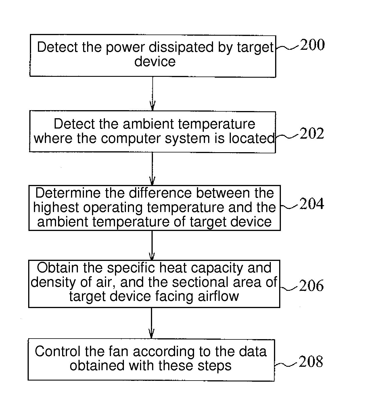
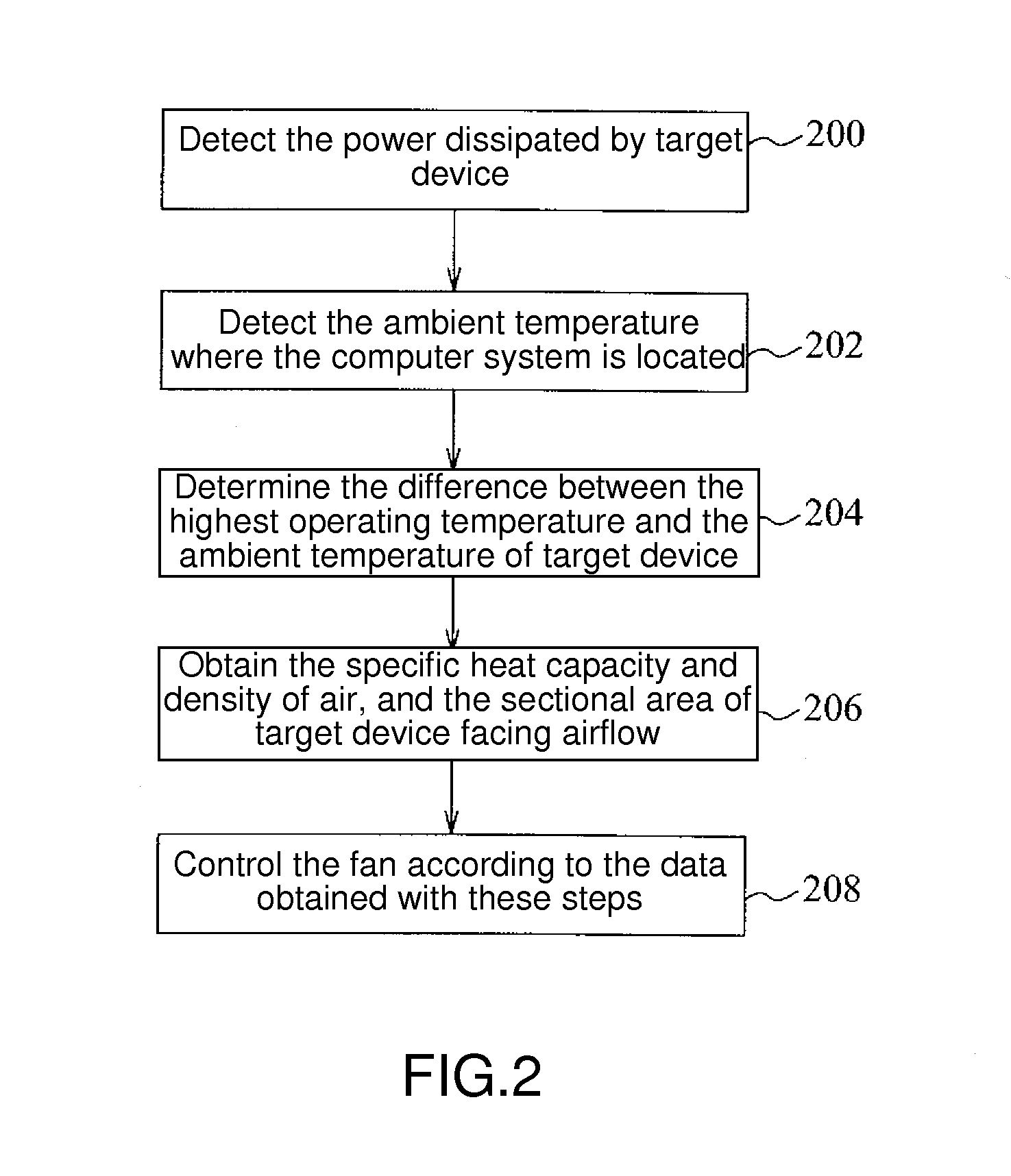
[0005]In one aspect, a fan control system and method is provided to determine an acceptable temperature raising range, and to prevent the fan from excess operating to achieve energy saving, and also reduce the noise generated by the fan. Another aspect provides a fan control system and method, which considers more full-scale factors to provide sufficient cooling airflow to a target device, such as a CPU, preventing overheated.

Problems solved by technology

Particularly, for the existed central processing unit (CPU) or storage device, such as memory or hard disk, due to the increased processing speed and correspondingly the resulted high temperature.
However, the prior art does not disclose the actual heat dissipation demand considering the operation of a target device, so as to provide sufficient cooling airflow to the target device within an acceptable temperature raising range, and achieve the effect of more energy saving at the same time.

Method used


Image

  • Fan control system and method for a computer system
  • Fan control system and method for a computer system
  • Fan control system and method for a computer system

Examples


Embodiment Construction

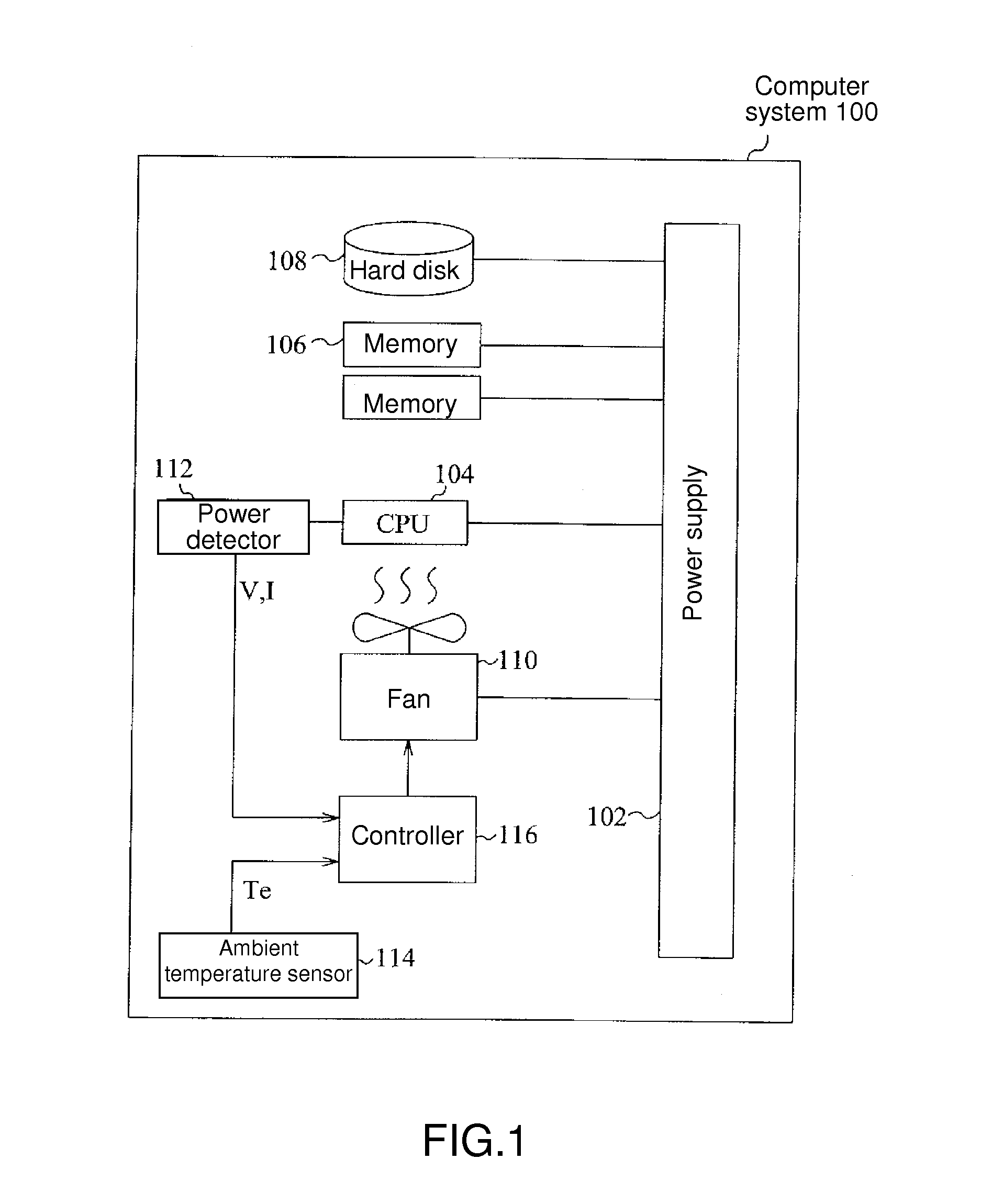
[0015]FIG. 1 shows hardware architecture of a computer system (100) in an embodiment, which comprises a power supply (102), a CPU (104), a memory (106), a hard disk (108), a fan (110), a power detector (112), an ambient temperature sensor (114), and a controller (116). Other basic architectures and components for computer system 100 may be referred to an ordinary personal computer or server, such as System X®, Blade Center® or eServer® server from IBM Corp. The details not related to the present invention will be omitted without description.

[0016]When a computer system (100) is operating, the power supply (102) provides direct current power to CPU (104), memory (106), hard disk (108), and a fan (110). It should be noted that the memory (106), the hard disk (108) and the fan (110) could be called target devices in the specification, because they will generate a large amount of heat during operating. The purpose of the fan (110) is to cool down these target devices. In an embodiment s...


PUM


Abstract

A fan control system for a computer system is provided. The fan control system includes a power sensor and a controller. The power sensor detects the power dissipated by a target device in the computer system. The controller calculates a suggested airflow speed required for the target device and thus outputs a control signal for controlling a fan within the computer system according to at least the dissipated power.

Description

TECHNICAL FIELD[0001]The present invention relates to a fan control system and method for a computer system.BACKGROUND OF THE INVENTION[0002]Generally, a computer system, for example a personal computer or high-end server, will have a cooling fan installed inside the system for heat dissipation. Particularly, for the existed central processing unit (CPU) or storage device, such as memory or hard disk, due to the increased processing speed and correspondingly the resulted high temperature. It is further required for employing a cooling fan to enhance the effect of heat dissipation to prevent the system damage due to being overheated.[0003]Some prior art employ a thermal diode, or DTS (Digital thermal Sensor), or PECI (Platform Environment Control Interface) provided by Intel Corp. to monitor the temperature of a device (such as CPU) and to control the cooling fan. When the temperature of the device is high, the DTS or PECI will control the fan to provide more airflow. For example, th...

Claims


Application Information

Patent Timeline
IPC IPC(8): G05D23/19
CPCG05D23/1917Y02B60/1275G06F1/206Y02D10/00
Inventor AKLILU, AMEHACHIU, CHARLIE CCHUANG, KELVIN WPKING, KU-JEIKUNG, EDWARD YCPAN, BRYAN MH
Owner LENOVO GLOBAL TECH INT LTD
Learn More