
Programmable controller system

a controller and controller technology, applied in the field of programmable controller systems, can solve the problems of large amount of effort and inability to ensure the reliability of time lag data obtained in such conditions, and achieve the effects of low labor intensity, high reliability and constant operation

Active Publication Date: 2011-03-31
ORMON CORP
View PDF6 Cites 5 Cited by
  • Summary
  • Abstract
  • Description
  • Claims
  • Application Information

AI Technical Summary

Benefits of technology

[0035]With such construction, efforts for determining threshold value can be reduced, for example, in case of introduction, in the PLC system including this type of external equipment deterioration diagnosis function. Also, since its constant operation is assured during the introduction and during the system operation, data with high reliability can be collected.
[0046]With such structure, when application is made so that a predetermine signal edge is generated in the first terminal in the output unit, the first terminal in the input unit, and the second terminal in the input unit sequentially in order, the time lag (T1) is a value corresponding to amount of time required to be activated in actual since an activating instruction is given to the device and the time lag (T2) corresponds to amount of time required to ends operation since activation is started. Accordingly, the value of the deterioration characteristic amount (T1×T2) represents both of degree of deterioration of the actuator and degree of deterioration of the external equipment. Therefore, degree of deterioration can be accurately recognized.
[0050]With such structure, a preferable data logging operation can be carried out properly in the monitoring apparatus configured to be located on a communication path between the programmable controller apparatus and the remote input and output apparatus and passively monitor communication data therebetween.
[0052]With such structure, the threshold value setting support apparatus includes a data collecting device for collecting data corresponding to time lag or deterioration characteristic amount generated within the remote input and output device without requiring to add a data collection function to user program of the programmable controller system, a threshold value determination device for determining a deterioration diagnosis threshold value in use of a statistical method based on the data corresponding to the time lag or deterioration characteristic amount collected by the data collecting device, and a threshold value setting device for setting the deterioration diagnosis threshold value determined by the threshold value determination device to the remote input and output apparatus. Accordingly, efforts for determining threshold value can be reduced, for example, in case of introduction, in the PLC system including this type of external equipment deterioration diagnosis function. Also, threshold value can be determined without waiting for, as conventional, large amount of data stored by logging process, so that amount of time required for determining threshold value can be reduced. Further, since its constant operation is assured during the introduction and during the system operation, data with high reliability can be collected.
[0054]With such structure, since threshold value is determined with reference to the standard deviation and the variation coefficient, the determined threshold value distinguishes deterioration state and non-deterioration state. Therefore, the reliability of deterioration diagnosis result can be improved.
[0056]According to the present invention, efforts for determining threshold value can be reduced, for example, in case of introduction, in the PLC system including this type of external equipment deterioration diagnosis function. Also, since its constant operation is assured during the introduction and during the system operation, data with high reliability can be collected.

Problems solved by technology

Therefore, when a plurality of remote input / output apparatuses exist and a plurality of subjects of deterioration diagnosis exist in each apparatus, programs shown in FIG. 10 for respective subjects of deterioration diagnosis is required to be written in user program, so that large amount of effort is required.
Accordingly, cycle time in the PLC apparatus will be slightly varies from the cycle time when the system is operative and reliability of time lag data obtained in such condition cannot be always assured.

Method used


Image

  • Programmable controller system
  • Programmable controller system
  • Programmable controller system

Examples


Embodiment Construction

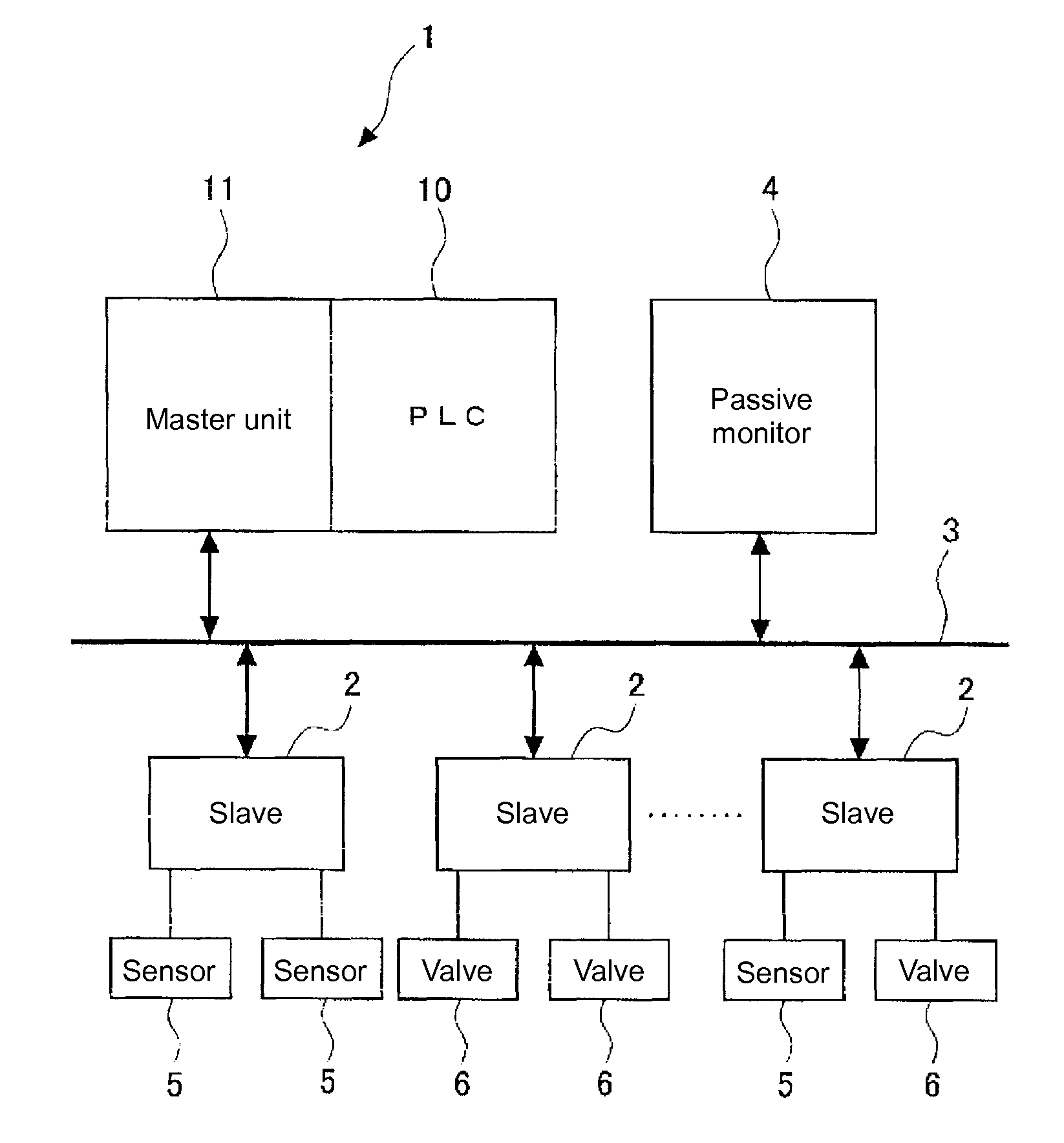
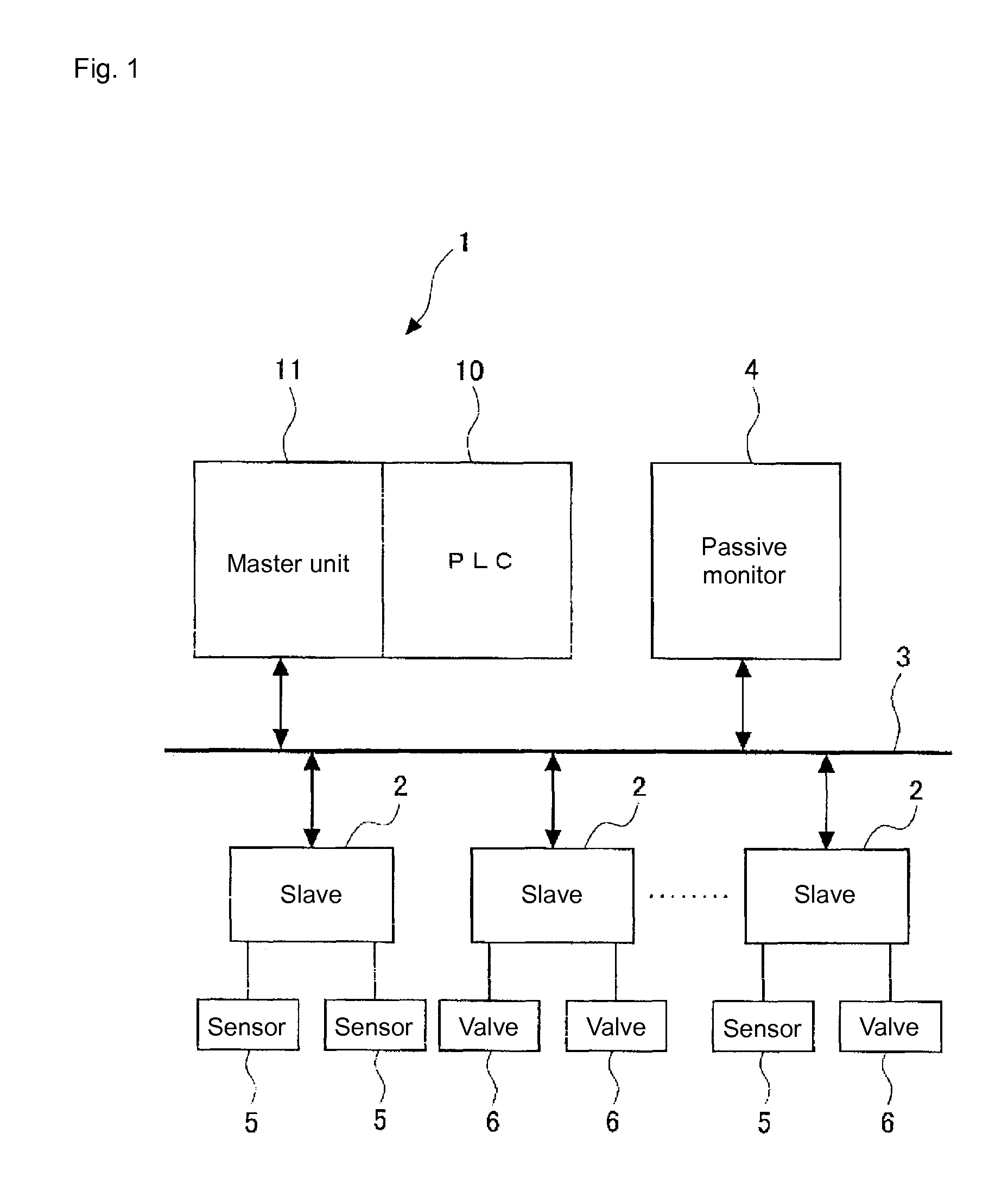
[0076]A preferred embodiments of the present invention will be explained in detail with reference to the drawings. A structural diagram of a PLC system according to the present invention is shown in FIG. 1.

[0077]As shown in FIG. 1, in the PLC system, a PLC apparatus 1 and a plurality of slaves (remote input / output apparatuses) 2 communicate each other via a field bus 3 and, a passive monitor 4 is provided on a communication paths between the PLC apparatus 1 and the slaves 2 for passively monitoring communication data transmitted therebetween.

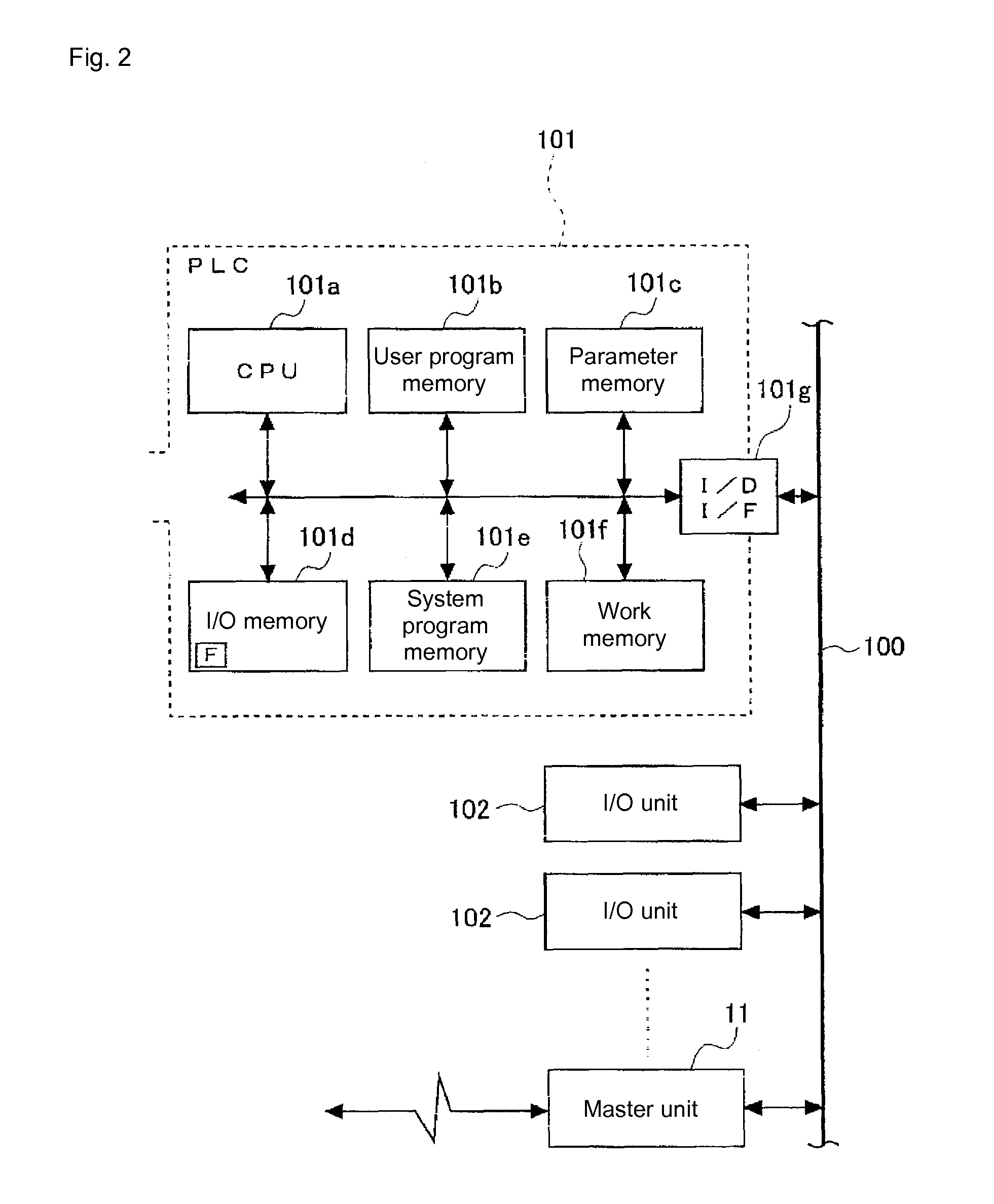
[0078]In the present embodiment, the PLC apparatus 1 is composed of a PLC 10 and a master unit 11. As shown in FIG. 2, the PLC 10 includes a CPU unit 101 for integrated control of the entire PLC and a plurality of I / O units 102, 102, . . . for operating as input units for receiving signals from external equipments and output units for transmitting signals to the external equipments.

[0079]As shown in FIG. 2, the CPU unit 101 includes a CPU 101a f...


PUM


Abstract

A programmable controller system includes a programmable controller apparatus, a remote input and output apparatus connected to the programmable controller apparatus via a field bus and a monitoring apparatus configured to be located on a communication path between the programmable controller apparatus and the remote input and output apparatus and to monitor a communication data therebetween. The monitoring apparatus includes a rewritable tag for prescribing a condition for issuing a transmission request command with respect to an external equipment deterioration diagnosis and a command issuing part issues a transmission request command required for the external equipment deterioration diagnosis with reference to the tag. A preferable data logging operation is carried out properly without any PLC operation.

Description

CROSS-REFERENCE TO RELATED PATENT APPLICATIONS[0001]Japan Priority Application P2005-072094, filed Mar. 14, 2005 and Japan Priority Application P2005-072096, filed Mar. 14, 2005 including the specification, drawings, claims and abstract, are incorporated herein by reference in their entirety. This application is a Divisional of U.S. application Ser. No. 11 / 373,507, filed Mar. 13, 2006, incorporated herein by reference in its entirety.BACKGROUND OF THE INVENTION[0002]1. Field of the Invention[0003]The present invention relates to a programmable controller system configured to notify deterioration diagnosis result of an external equipment implemented by a remote input / output apparatus to a programmable controller apparatus via communication path, so that the deterioration diagnosis result can be referred directly with a ladder diagram.[0004]2. Description of the Related Art[0005]Prior to this application, the applicant has proposed a programmable controller system (hereinafter, referr...

Claims


Application Information

Patent Timeline
Patent Type & Authority Applications(United States)
IPC IPC(8): G06F17/18
CPCG05B19/058G05B2219/14112G05B2219/14057
Inventor UENO, SHINTAROIZUTANI, HAJIME
Owner ORMON CORP
Learn More