Systems and methods for scenario-based process modeling

a process modeling and scenario-based technology, applied in the field of scenario-based process modeling, can solve the problems of not allowing end-user-driven process composition, affecting the implementation of bpm solutions in enterprises, and inacceptable for business users

Active Publication Date: 2011-03-31
SAP AG
View PDF10 Cites 55 Cited by
  • Summary
  • Abstract
  • Description
  • Claims
  • Application Information

AI Technical Summary

Problems solved by technology

Existing tools for process modeling, for example, TIBCO® Business Studio (TIBCO®, 2007), JBoss® JBPM (JBoss®, 2007), Soyatec® eBPMN Designer (Soyatec®, 2007), STP BPMN Modeler (STP, 2007) do not allow end-user-driven process composition.
These tools require process designers to understand specific modeling notation, to explicitly enter the process modeling environment, which may be unacceptable for business users, who are focused on executing business tasks and not on modeling processes.
Although effective BPM can generate business value in organizations, issues can arise that can jeopardize the implementation of BPM solutions in enterprises.
One issue is the difficulty in explicating all needed information for process design, but an even more difficult task can involve the transfer of the process requirements from the business users to process designers and developers involved in a workflow automation project.
One of the difficulties in involving end users in the design and definition of business processes is that the process often demands both domain expertise and advanced computer skills.
Therefore conventional workflow modeling through visual languages (e.g., the Business Process Modeling Notation (BPMN) from the Object Management Group, http: / / www.bpmn.org) is inappropriate for process tailoring by end users.
The challenge is to enable scenario authoring, which is easy for end users to use and at the same time adequately translates scenario descriptions into formal process models.
In some examples, choosing a particular consolidation option may result in further inconsistent task relationships that will prompt further consolidation options.
In some examples, the consolidation process may cause additional inconsistent relationships that did not explicitly exist prior to consolidation.

Method used


Image

  • Systems and methods for scenario-based process modeling
  • Systems and methods for scenario-based process modeling
  • Systems and methods for scenario-based process modeling

Examples


example consolidation

Options

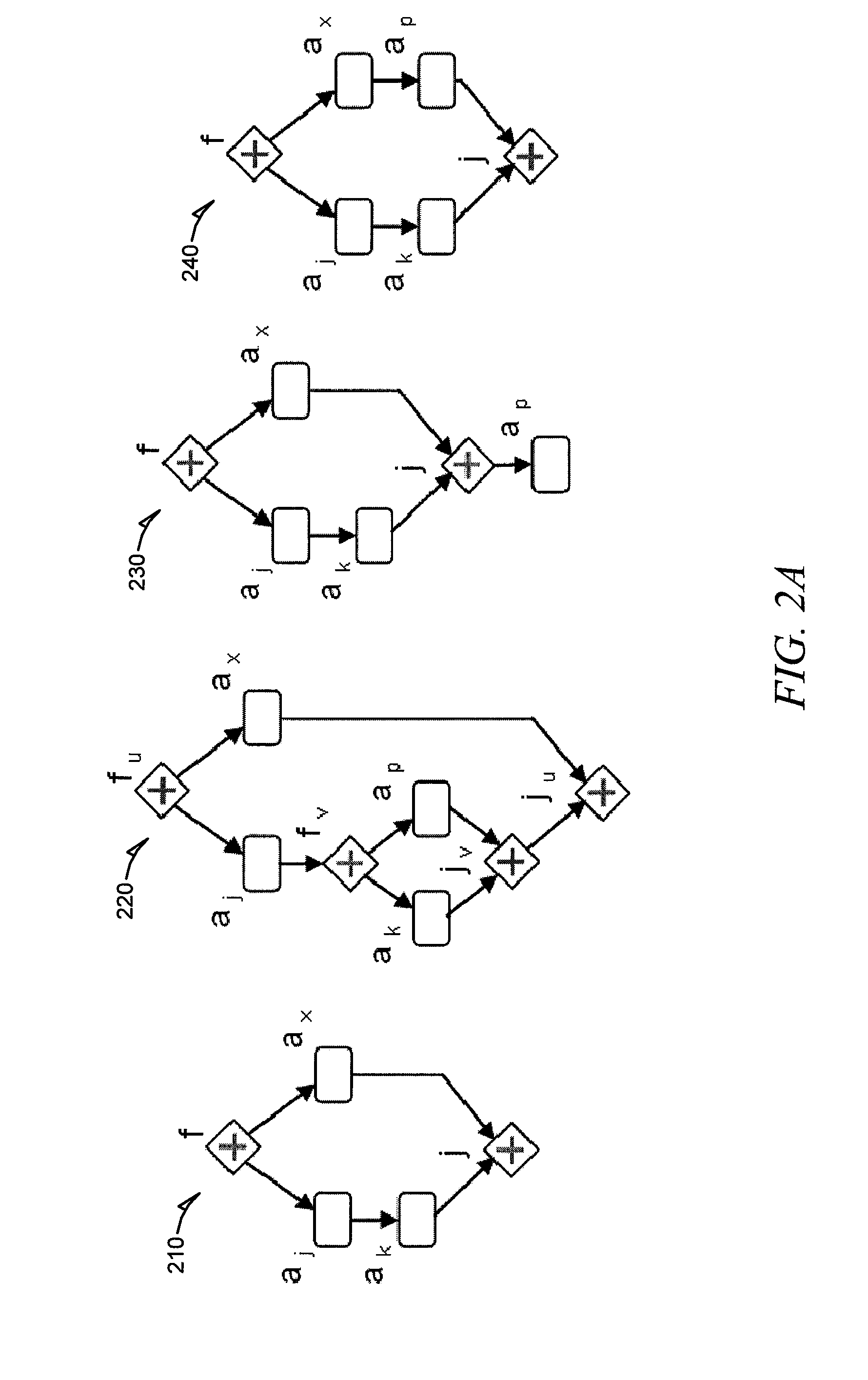
[0053]FIG. 2D is a set of workflow graphs illustrating consolidation options, according to an example embodiment. The following example consolidations are in comparison to workflow graph 240, illustrated in FIG. 2A. One type of consolidation can be referred to as a merge. A merge is typically used to extend parallel relationships. In an example, three types of merge consolidations for extending parallel relationship can be used, merge head, merge tail, and merge tail to head. Merge head consolidation adds parallelism between Aj and Ak, as shown by workflow graph 215. Merge tail consolidation adds parallelism between Ax and Ap, as shown by workflow graph 225. Merge tail to head consolidation adds parallelism between Aj and Ap, as shown by example workflow graph 235.

[0054]Another type of consolidation is a split, which can be used to remove parallel relationships. As an alternative to the merge consolidations the following three types of split consolidations can be used to remo...

example implementation

[0061]The following example implementation uses a Collaborative Task Manager (CTM) prototype with a user interface component called a Process Definition Wizard (PDW).

Defining the Normal Scenario

[0062]FIG. 3 is a user interface screen 300 illustrating the definition of a normal scenario within the process definition wizard (PDW), according to an example embodiment. The user interface 300 includes a workflow definition bar 310, a scenario toolbar 320, a task toolbar 330, a tab pane 340, and a task list 350. The workflow definition bar 310 includes a workflow definition procedure with four steps. In this example, the workflow definition bar 310 includes a back button 312 and a next button 314 for moving back and forth between the steps. The user interface screen 300 illustrates the “Define normal scenario” step, shown highlighted. The scenario toolbar 320 displays the current scenario in the drop-down list 322. The drop-down list 322 can display a list that contains all generated scena...


PUM


Abstract

Methods and systems for scenario-based process modeling are described. In one example embodiment, a system for scenario-based process modeling can include a scenario module, a deviations module, a parallel tasks module, and a workflow generation engine. The scenario module is to receive a series of tasks to define a standard process flow. The deviations module is to receive a deviation from the standard process flow. The parallel tasks module is to enable identification of one or more parallel tasks. The workflow generation engine is to generate a workflow model based on the standard process flow, deviation, and one or more parallel tasks.

Description

COPYRIGHT NOTICE[0001]A portion of the disclosure of this patent document contains material that is subject to copyright protection. The copyright owner has no objection to the facsimile reproduction by anyone of the patent document or the patent disclosure, as it appears in the Patent and Trademark Office patent files or records, but otherwise reserves all copyright rights whatsoever. The following notice applies to the software and data as described below and in the drawings that form a part of this document: Copyright 2009, SAP AG. All Rights Reserved.TECHNICAL FIELD[0002]Various embodiments relate generally to the field of business process modeling, and in particular, but not by way of limitation, to a system and method for scenario-based process modeling.BACKGROUND[0003]Business process modeling is intended to represent real-world processes of an enterprise on paper or within a computer system. Business process modeling is typically performed to analyze and improve current ente...

Claims


Application Information

Patent Timeline
Patent Type & Authority Applications(United States)
IPC IPC(8): G06F9/46G06F9/38
CPCG06F8/10G06Q10/04G06Q10/00
Inventor STOITSEV, TODOR
Owner SAP AG
Why Eureka
Try Eureka