Systems and methods for combined thermal and compressed gas energy conversion systems

a technology of energy conversion system and compressed gas, which is applied in the direction of mechanical power devices, mechanical equipment, mechanical power devices, etc., can solve the problems of inadvertent brownouts and blackouts, burnt expensive fuels, natural gas, etc., and achieve cost-effective and efficient energy storage. , the effect of increasing the power density and efficiency

Inactive Publication Date: 2011-04-07
SUSTAINX
View PDF105 Cites 41 Cited by
  • Summary
  • Abstract
  • Description
  • Claims
  • Application Information

AI Technical Summary

Benefits of technology

[0014]The invention overcomes the disadvantages of the prior art by combining systems for thermal energy recovery, extraction, and / or usage with a system and method for compressed-gas energy storage to allow for cost-effective and efficient energy storage. In the invention, the heat-exchange subsystem of a novel compressed-gas energy conversion system, a staged hydraulic / pneumatic system as described in U.S. Provisional Patent Application No. 61 / 043,630 with heat transfer circuit as described in U.S. Provisional Patent Application No. 61 / 059,964—both applications of which are hereby incorporated by reference in their entireties—is combined with thermal systems to increase power density and efficiency by utilizing said thermal systems to chill or heat the transfer medium (e.g., water). In one application, excess thermal energy (e.g., waste heat) from power plants or industrial processes is used to preheat the heat-exchange fluid in the compressed-gas energy conversion system's heat-exchange subsystem. In such instances, the power density of the energy conversion system can be increased by coupling this excess thermal energy with the system while expanding stored gas. Similarly, chilled water that may be available from the natural local environment (e.g., a river) can be used to pre-cool the heat exchange fluid to decrease power requirements during compression. In the absence of such heating or cooling sources, both pre-heated and pre-chilled water can be efficiently generated through the use of heat pumps. Alternatively, hot and cold water generated during compression and expansion cycles, respectively, can be used as a heating or cooling source. Heated water (from the heat exchange subsystem during compression) can be used for process heat or building conditioning, and cooled water (from the heat exchange subsystem during expansion) can be used for cooling systems and / or building conditioning. In all instances, the combination of systems for thermal energy recovery, extraction, and / or usage with a compressed-gas energy conversion system improves performance and cost effectiveness.
[0015]In one application, excess thermal energy (e.g., waste heat) from power plants or industrial processes is used to preheat the heat exchange fluid and / or the compressed gas in the compressed-gas energy conversion system's heat-exchange subsystem. In such instances, the power density of the energy conversion system may be increased by coupling this excess thermal energy with the system during expansion of stored gas. Similarly, chilled water, such as may be available from the natural local environment (e.g., from a river), may be used to pre-cool the heat exchange fluid, the stored compressed gas prior to further compression, and / or the compressed gas during compression to decrease power requirements during compression. In the absence of such heating or cooling sources, heated and chilled water may be efficiently generated using ground loops, water loops, heat pumps, or other means. Alternatively, hot and cold water generated during compression and expansion cycles, respectively, may be used as a heating or cooling source. Heated water (from the heat exchange subsystem during compression) may be used for process heat or building conditioning, and cooled water (from the heat exchange subsystem during expansion) may be used for cooling systems and / or building conditioning. In all instances, the combination of systems for thermal energy recovery, extraction, and / or usage with a compressed-gas energy conversion system improves performance and cost effectiveness.

Problems solved by technology

In certain parts of the United States, inability to meet peak demand has led to inadvertent brownouts and blackouts due to system overload as well as to deliberate “rolling blackouts” of non-essential customers to shunt the excess demand.
However, these units burn expensive fuels, such as natural gas, and have high generation costs when compared with coal-fired systems and other large-scale generators.
Accordingly, supplemental sources have economic drawbacks and, in any case, can provide only a partial solution in a growing economy.
The most obvious solution involves construction of new power plants, which is expensive and has environmental side effects.
In addition, because most power plants operate most efficiently when generating a relatively continuous output, the difference between peak and off-peak demand often leads to wasteful practices during off-peak periods, such as over-lighting of outdoor areas, as power is sold at a lower rate off peak.
As demand for renewable energy increases, the intermittent nature of some renewable energy sources (e.g., wind and solar) places an increasing burden on the electric grid.
However, the need to burn fossil fuel (or apply another energy source, such as electric heating) to compensate for adiabatic expansion substantially defeats the purpose of an emission-free process for storing and recovering energy.
While it is technically possible to attach a heat-exchange subsystem directly to a hydraulic / pneumatic cylinder (an external jacket, for example), such an approach is not particularly effective given the thick walls of the cylinder.
An internalized heat exchange subsystem could conceivably be mounted directly within the cylinder's pneumatic (gas-filled) side; however, size limitations would reduce such a heat exchanger's effectiveness and the task of sealing a cylinder with an added subsystem installed therein would be significant, making the use of a conventional, commercially available component difficult or impossible.
However, the prior art does not disclose systems and methods for increasing efficiency and power density in isothermal compressed-gas-based energy storage systems having heat exchangers by heating or cooling the heat-transfer fluid.

Method used


Image

  • Systems and methods for combined thermal and compressed gas energy conversion systems
  • Systems and methods for combined thermal and compressed gas energy conversion systems
  • Systems and methods for combined thermal and compressed gas energy conversion systems

Examples


Embodiment Construction

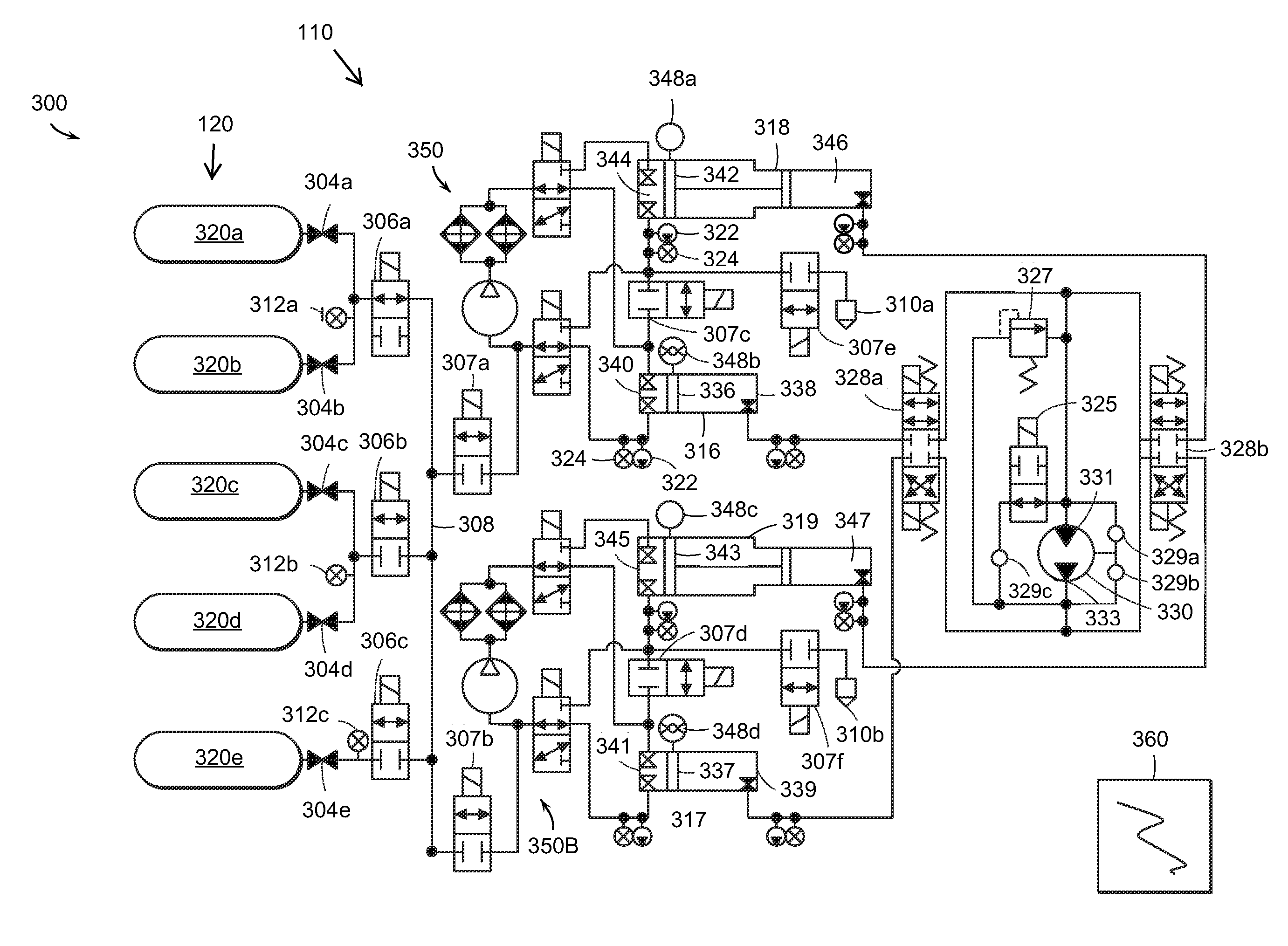
[0041]In the following, various embodiments of the present invention are generally described with reference to a single hydraulic cylinder (for example, an accumulator or an intensifier) and simplified valve arrangements. It is, however, to be understood that embodiments of the present invention may include any number and combination of accumulators, intensifiers, and valve arrangements. In addition, any dimensional values given are exemplary only, as the systems according to the invention are scalable and customizable to suit a particular application. Furthermore, the terms pneumatic, gas, and air are used interchangeably and the terms hydraulic and fluid are also used interchangeably.

[0042]The temperature of the compressed air stored in the system can be related to its pressure and volume through the ideal gas law and thus to the power output of the system during expansion. Therefore, pre-heating (before nor during expansion) or pre-cooling (during compression) of the compressed g...


PUM


Abstract

The invention relates to systems and methods including an energy conversion system for storage and recovery of energy using compressed gas, a source of recovered thermal energy, and a heat-exchange subsystem in fluid communication with the energy conversion system and the source of recovered thermal energy.

Description

CROSS-REFERENCE TO RELATED APPLICATIONS[0001]This application claims priority to U.S. Provisional Patent Application Ser. No. 61 / 145,860, filed on Jan. 20, 2009; U.S. Provisional Patent Application Ser. No. 61 / 145,864, filed on Jan. 20, 2009; U.S. Provisional Patent Application Ser. No. 61 / 146,432. filed on Jan. 22, 2009; U.S. Provisional Patent Application Ser. No. 61 / 148,481, filed on Jan. 30, 2009; U.S. Provisional Patent Application Ser. No. 61 / 151,332, filed on Feb. 10, 2009; U.S. Provisional Patent Application Ser. No. 61 / 227,222, filed on Jul. 21, 2009; U.S. Provisional Patent Application Ser. No. 61 / 256,576, filed on Oct. 30, 2009; U.S. Provisional Patent Application Ser. No. 61 / 264,317, filed on Nov. 25, 2009; and U.S. Provisional Patent Application Ser. No. 61 / 266,758, filed on Dec. 4, 2009; the disclosure of each of which is hereby incorporated herein by reference in its entirety.STATEMENT REGARDING FEDERALLY SPONSORED RESEARCH[0002]This invention was made with government...

Claims


Application Information

Patent Timeline
Patent Type & Authority Applications(United States)
IPC IPC(8): F03G7/00F02G1/043
CPCF02C6/16F03G6/00Y02T10/16Y02E10/46Y02E60/15F03G7/04Y02E60/16Y02T10/12F03G6/071F03G4/001
Inventor MCBRIDE, TROY O.BOLLINGER, BENJAMIN R.IZENSON, MICHAELCHEN, WEIBOMAGARI, PATRICKCAMERON, BENJAMIN
Owner SUSTAINX
Why Eureka
Try Eureka