Non-parabolic solar concentration to an area of controlled flux density conversion system and method

Inactive Publication Date: 2011-04-07
BRIGHTLEAF TECH
View PDF45 Cites 12 Cited by
  • Summary
  • Abstract
  • Description
  • Claims
  • Application Information

AI Technical Summary

Problems solved by technology

The high intensity light flux may damage or shorten the life of the photovoltaic cell 36 by direct exposure or heat buildup in the module 32.

Method used


Image

  • Non-parabolic solar concentration to an area of controlled flux density conversion system and method
  • Non-parabolic solar concentration to an area of controlled flux density conversion system and method
  • Non-parabolic solar concentration to an area of controlled flux density conversion system and method

Examples


example

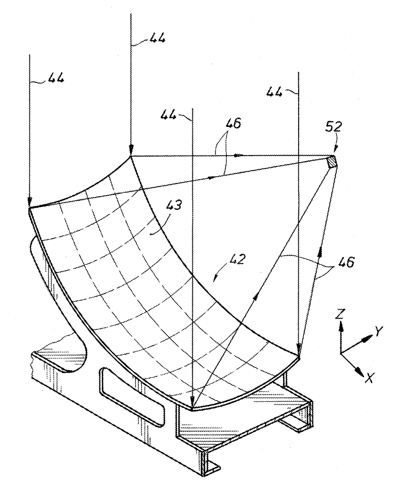
[0054]In one non-limiting example of the device disclosed herein, the collector 42 concentrates 650 suns on a solar cell having a 1 cm2 area. The collector 42 is a rectangular shaped stamped aluminum piece (approximately 14″ by 8″) constituting a non-parabolic solid. The solid is coated with a reflective coating with reflectivity of approximately 95%. This piece is designed to create a square beam which converges on a focal plane 1 cm2 some inches to the side of the collector 42. The design of the collector 42 creates an even energy flux across the entire span of the focal plane without the interposition of any corrective optics (e.g., a homogenizer or diffuser). An optical lens may be placed in front of the focal plane to protect the cell from weather. A typical mounting configuration would place eight rectangles, one above the other, with another eight high array set by its side at 180° orientation. A multijunction cell mounts on a bracket at the focal plane of the collector 42. T...


PUM


Abstract

A solar conversion system with a solar collector that is shaped to focus reflected sunlight along an area with a substantially constant flux density. The area shape can be resemble a rectangular, square, circular, or other shape. Included with the system is a solar conversion module having a photovoltaic cell that is alignable with the area. The cell converts the focused reflected sunlight into electrical energy when aligned with the area.

Description

RELATED APPLICATIONS[0001]This application claims priority to and the benefit of co-pending U.S. Provisional Application Ser. No. 61 / 249,202, filed Oct. 6, 2009, the full disclosure of which is hereby incorporated by reference herein.BACKGROUND OF THE INVENTION[0002]1. Field of the Invention[0003]The present disclosure relates in general to a solar conversion system that concentrates solar energy non-parabolically and converts the concentrated energy into electrical energy. More specifically, the present disclosure includes a solar conversion system having a non-parabolic solar collector that concentrates reflected solar energy into a focal area of controlled flux density.[0004]2. Description of Prior Art[0005]FIG. 1A illustrates a prior art view of a solar conversion system 20 shown in a side perspective view. The solar conversion system 20 includes a parabolic dish 22 having a reflective surface 24 on its concave side that reflects sun rays 26 to form reflected rays 28. The dish 2...

Claims


Application Information

Patent Timeline
IPC IPC(8): H01L31/052F24S23/70
CPCF24J2/10F24J2/523F24J2002/1014H01L31/0547H01L31/0525Y02E10/52Y02E10/47F24J2002/108F24S23/70F24S25/10F24S2023/832F24S2023/872
Inventor VANDER MEY, JAMES E.KIESEWETTER, JR., DOUGLAS HELFFDUCKWORTH, SHANE MARK
Owner BRIGHTLEAF TECH
Why Eureka
Try Eureka