Swing arm style tire changer

Active Publication Date: 2011-04-07
SHANGHAI BALANCE AUTOMOTIVE EQUIP
View PDF5 Cites 2 Cited by
  • Summary
  • Abstract
  • Description
  • Claims
  • Application Information

AI Technical Summary

Benefits of technology

[0006]The invention is advantageous in that it provides a swing arm style tire changer comprising a tire changer head which is not

Problems solved by technology

As a result, the swing arm and the upright stem are easily deformed and distorted in shape caused by the force during the mounting or dismounting action, causing the tire changer head direc

Method used


Image

  • Swing arm style tire changer
  • Swing arm style tire changer
  • Swing arm style tire changer

Examples


Embodiment Construction

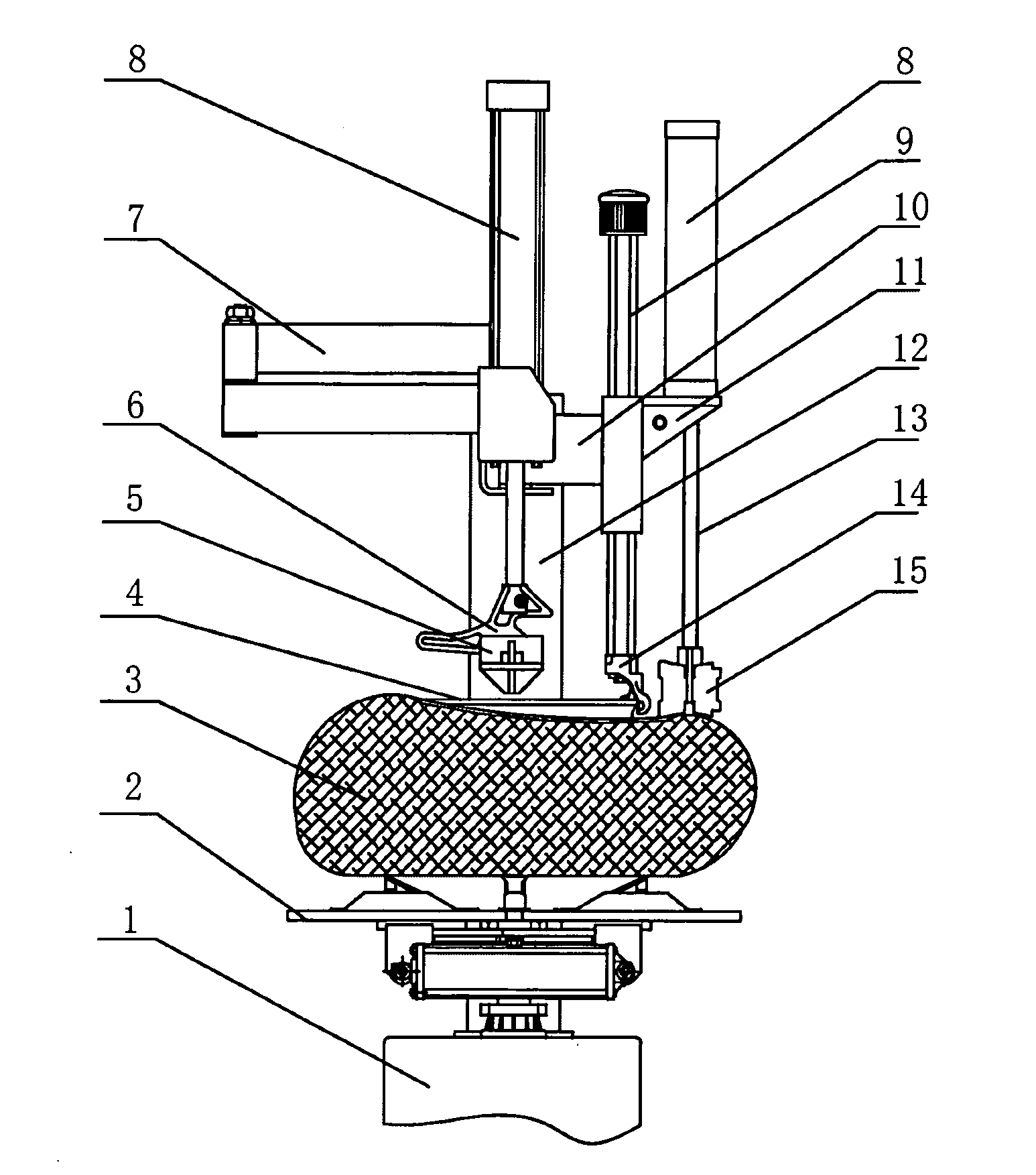
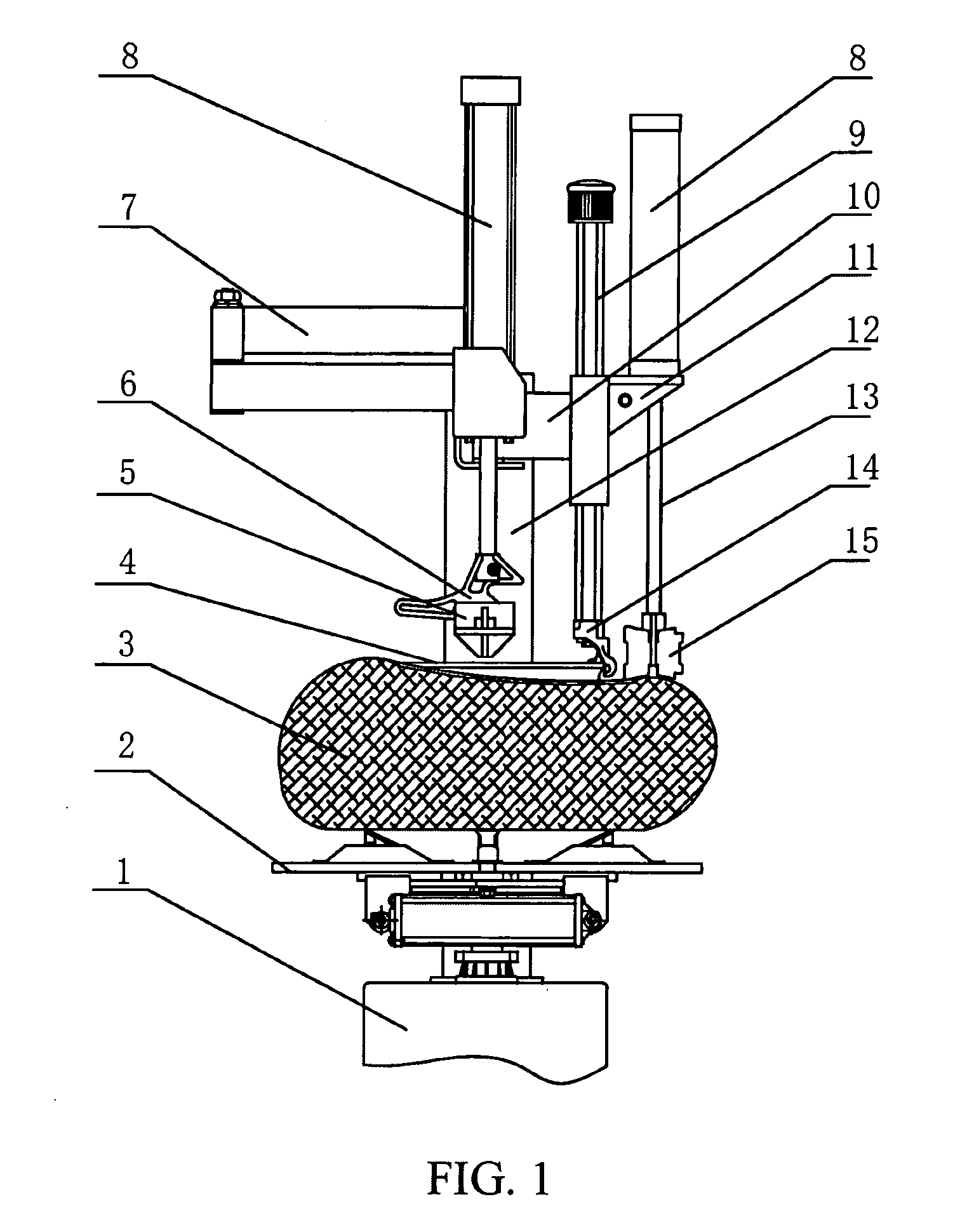
[0022]Referring to FIG. 1 of the drawings, a swing arm style tire changer of a preferred embodiment of the present invention comprises a base 1, a swing arm 10 and a tire changer arm 9. The base 1 having a base body comprises a work-bench 2 supported by the base body and an upright stem 12 mounted onto the base body, wherein the work-bench 2 is connected to a transmission system of the base body and operatively connected with the base body in such a manner that the work-bench 2 is capable of rotating along a vertical axis defined by the base body. In other words, the work bench 2 is rotatably mounted on the base body, adapted for rotating relative to the base body horizontally while being supported by the base body. The work-bench 2 comprises a positioning unit adapted for positioning a rim body 4 of a tire object, such that when the rim body 4 of the tire object is securely positioned on the work-bench 2 through the positioning unit, the rim body 4 will be guided to rotate along wi...


PUM


Abstract

A swing arm style tire changer includes a base (1), a workbench (2), an upright stem (12), a swing arm (10) and a dismounting head (14). The swing arm (10) is attached to the upright stem (12) and is capable of rotating horizontally. The swing arm style tire changer also includes a first helper arm (11) connected to the swing arm (10); under said first helper arm (11) and connected thereto is a tire-pressing wheel (15) that may be moved vertically upwards and downwards. The first helper arm (11) is attached to the swing arm (10) and is capable of rotating horizontally, and a pneumatic cylinder (8) is arranged on said first helper arm (11). The swing arm style tire changer also includes a second helper arm (7).

Description

BACKGROUND OF THE PRESENT INVENTION[0001]1. Field of Invention[0002]The present invention relates to a device for mounting and dismounting a tire member to and from a rim body of a tire object, and more particularly to a swing arm style tire changer.[0003]2. Description of Related Arts[0004]The economic development has led to the development and advancement of transportation in which the high volume use of vehicles has resulted in the greatly increasing need for tire repairing. The step of changing tire which used to be performed manually by labor is now performed by employing machinery which greatly reduces the labor requirement and hence increases the efficiency.[0005]The Chinese patent publication number CN2188045Y has disclosed a tire changer device which includes a base; a rotatable work-bench mounted on the base comprising a jaw unit for securing the position of the wheel body; an upright stem having a top end comprising a rotatable swing arm mounted thereon; a tire changer ar...

Claims


Application Information

Patent Timeline
IPC IPC(8): B60C25/132
CPCB60C25/138
Inventor XILIN, CAI
Owner SHANGHAI BALANCE AUTOMOTIVE EQUIP
Why Eureka
Try Eureka