Heat transfer device with functions of power generation

Inactive Publication Date: 2011-04-07
ELECTRONICS & TELECOMM RES INST
View PDF18 Cites 4 Cited by
  • Summary
  • Abstract
  • Description
  • Claims
  • Application Information

AI Technical Summary

Benefits of technology

[0012]The heat transfer device according to the present invention has a function of generating power through the vibration of the capillary grooves having a thin piezoelectric film deposited thereon, in addition to the heat transfer function of discharging the heat transferr

Problems solved by technology

However, when an electronic apparatus includes a plurality of heating elements for discharging a large amount of heat for a unit time, it is difficult to cool down the heat generated from the inside of the electronic apparatus with only the hea

Method used


Image

  • Heat transfer device with functions of power generation
  • Heat transfer device with functions of power generation
  • Heat transfer device with functions of power generation

Examples


Embodiment Construction

[0017]Hereinafter, an example embodiment of the present invention will be described in detail with reference to the accompanying drawings. However, it will be appreciated by those skilled in the art that various changes may be made to these example embodiments, and the scope of the present invention is not limited to the example embodiments. The example embodiments are provided to more clearly explain the present invention to those skilled in the art.

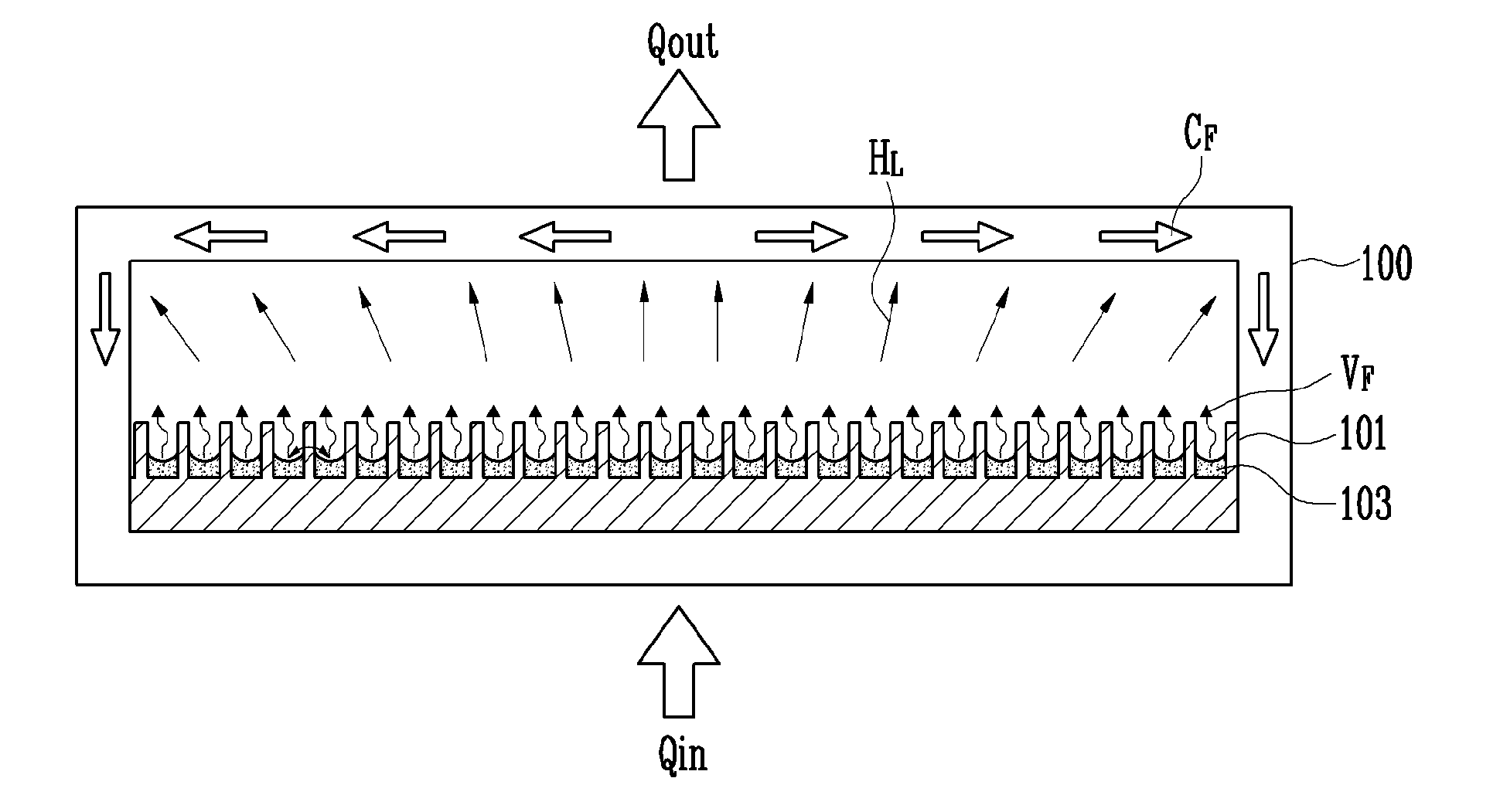
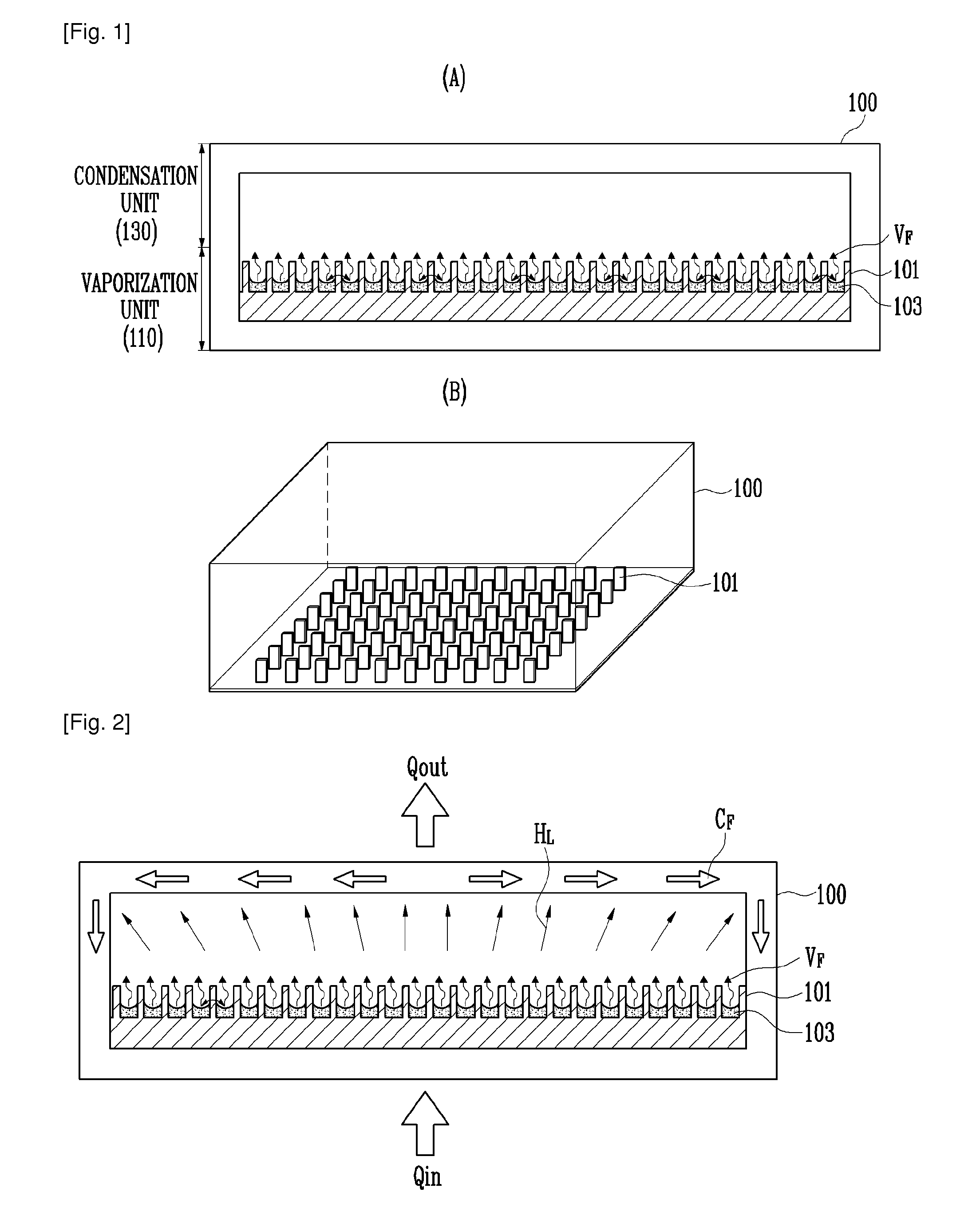
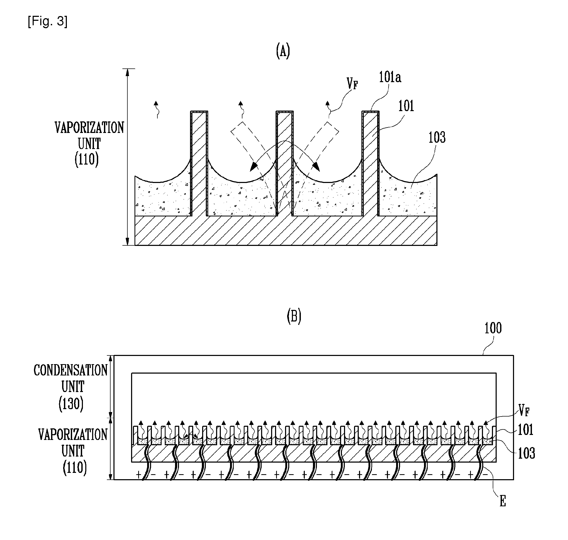
[0018]FIGS. 1A and 1B are schematic views of a heat transfer device capable of generating power according to the present invention. FIG. 2 is a diagram for explaining heat transfer operation of the heat transfer device according to the present invention.

[0019]Referring to FIGS. 1A and 1B, the heat transfer device 100 capable of generating power according to the present invention has an airtight structure of which the inner space is maintained in a vacuum state.

[0020]A working fluid 103 is injected into the heat transfer device 100 havin...


PUM

PropertyMeasurementUnit
Phaseaaaaaaaaaa
Piezoelectricityaaaaaaaaaa

Abstract

Provided is a heat transfer device which has a function of generating power through vibration of capillary grooves having a thin piezoelectric film deposited thereon, in addition to a heat transfer function of discharging heat transferred from a heating element to the outside.

Description

TECHNICAL FIELD[0001]The present invention relates to a heat transfer device capable of generating power, and more specifically, to a heat transfer device which not only has a heat transfer function of discharging heat transferred from a heating element to the outside, but also has a function of generating power through vibration of capillary grooves having a piezoelectric thin film deposited thereon.BACKGROUND ART[0002]Recently, as computers and various electronic apparatuses are becoming reduced in size, the internal structure thereof is being compactly integrated. Therefore, the temperature of semiconductor chips may increase due to heat generated from the inside of the electronic apparatuses. In this case, the performance of the semiconductor chips may be degraded, or the lifespan thereof may be reduced.[0003]To solve such an internal heat problem, a method of attaching a heat sink to a heating element has been conventionally used to cool down the heating element. However, when ...

Claims


Application Information

Patent Timeline
IPC IPC(8): F28D15/04
CPCF28D15/0233H02N2/18F28F2245/00F28D15/046F28D21/00H05K7/20
Inventor MOON, SEOK HWANHWANG, GUNN
Owner ELECTRONICS & TELECOMM RES INST
Why Eureka
Try Eureka