
Wafer storage container

a storage container and wafer technology, applied in the field can solve the problems of increased damage, deficiency gaps actually present for insertion and removal of wafer storage containers, etc., and achieve the effect of preventing the spread of fire to adjacent wafer storage containers

Active Publication Date: 2011-04-07
SHIN-ETSU POLYMER CO LTD
View PDF9 Cites 8 Cited by
  • Summary
  • Abstract
  • Description
  • Claims
  • Application Information

AI Technical Summary

Benefits of technology

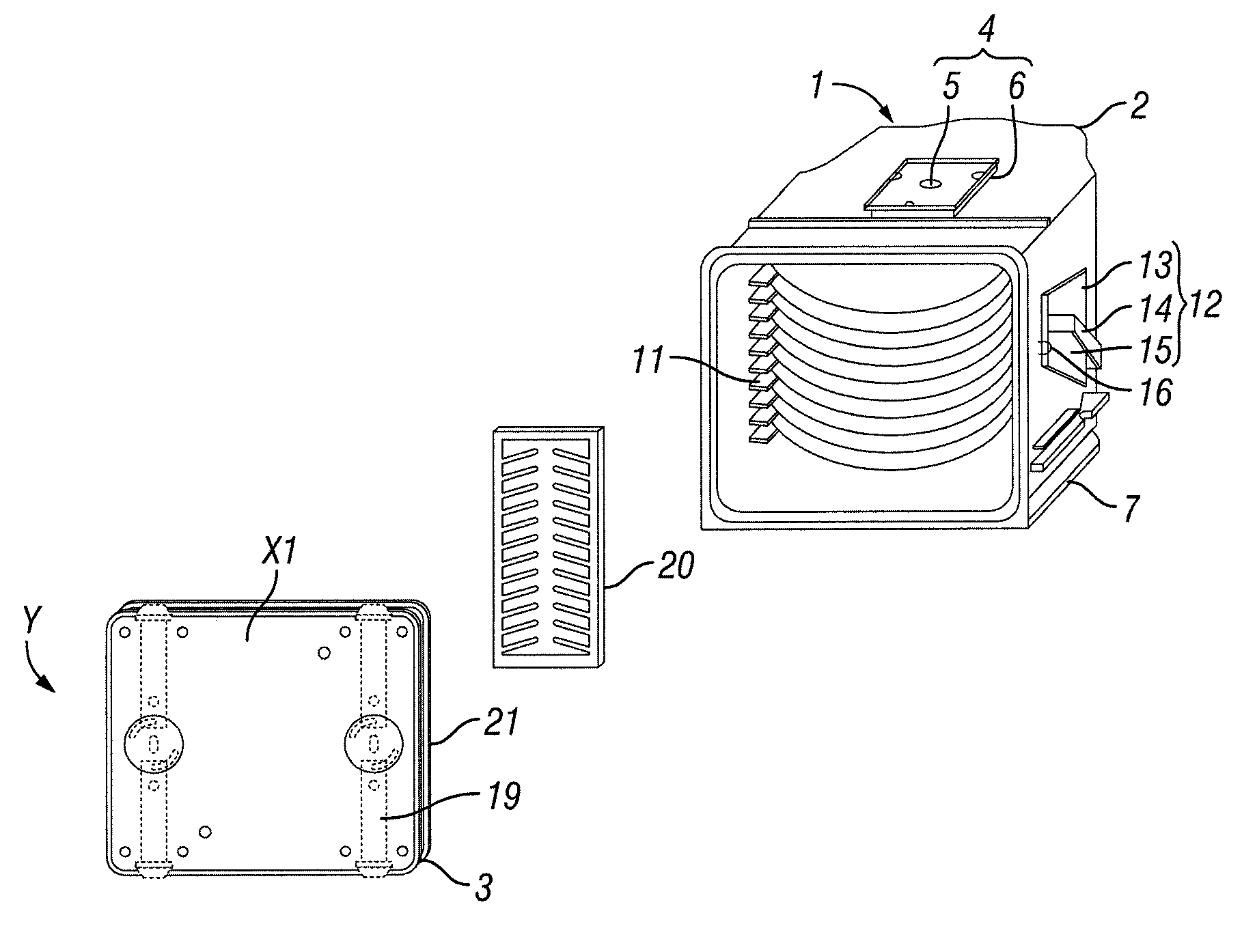
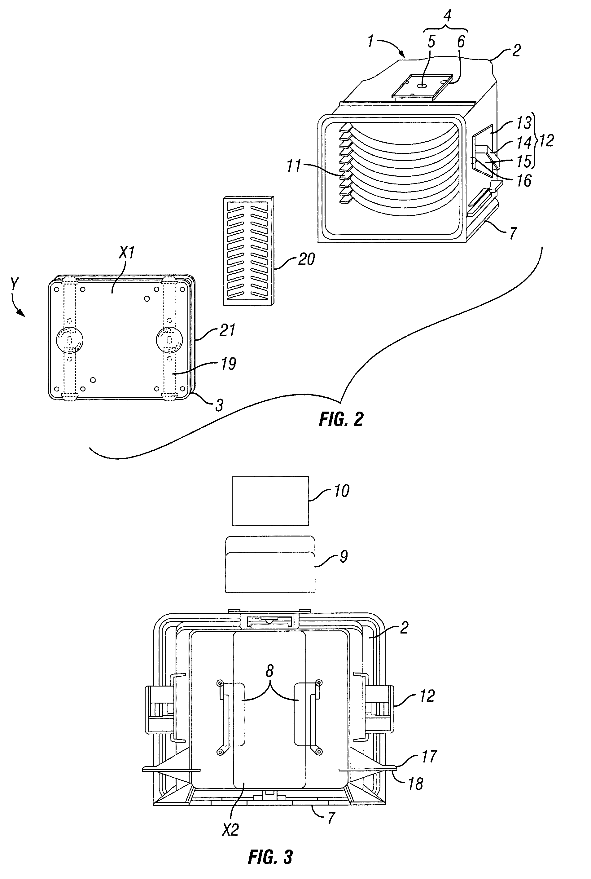
According to one or more embodiments of the present invention, because each of the types of attachment members provided at the exterior surface of the wafer storage container is formed from a self-extinguishing material, even if a flame is generated during storage of the wafer storage container, spread of fire to adjacent wafer storage containers can be effectively prevented. As the self-extinguishing material of this invention, polyetherimide and / or liquid crystal polymer may be preferably used.

Problems solved by technology

The above-described type of storage container is formed from synthetic resin that readily burns and causes increased damage when a fire occurs within a semiconductor manufacturing process while the wafer storage container is kept in storage at an in-process semiconductor manufacturing storage warehouse.
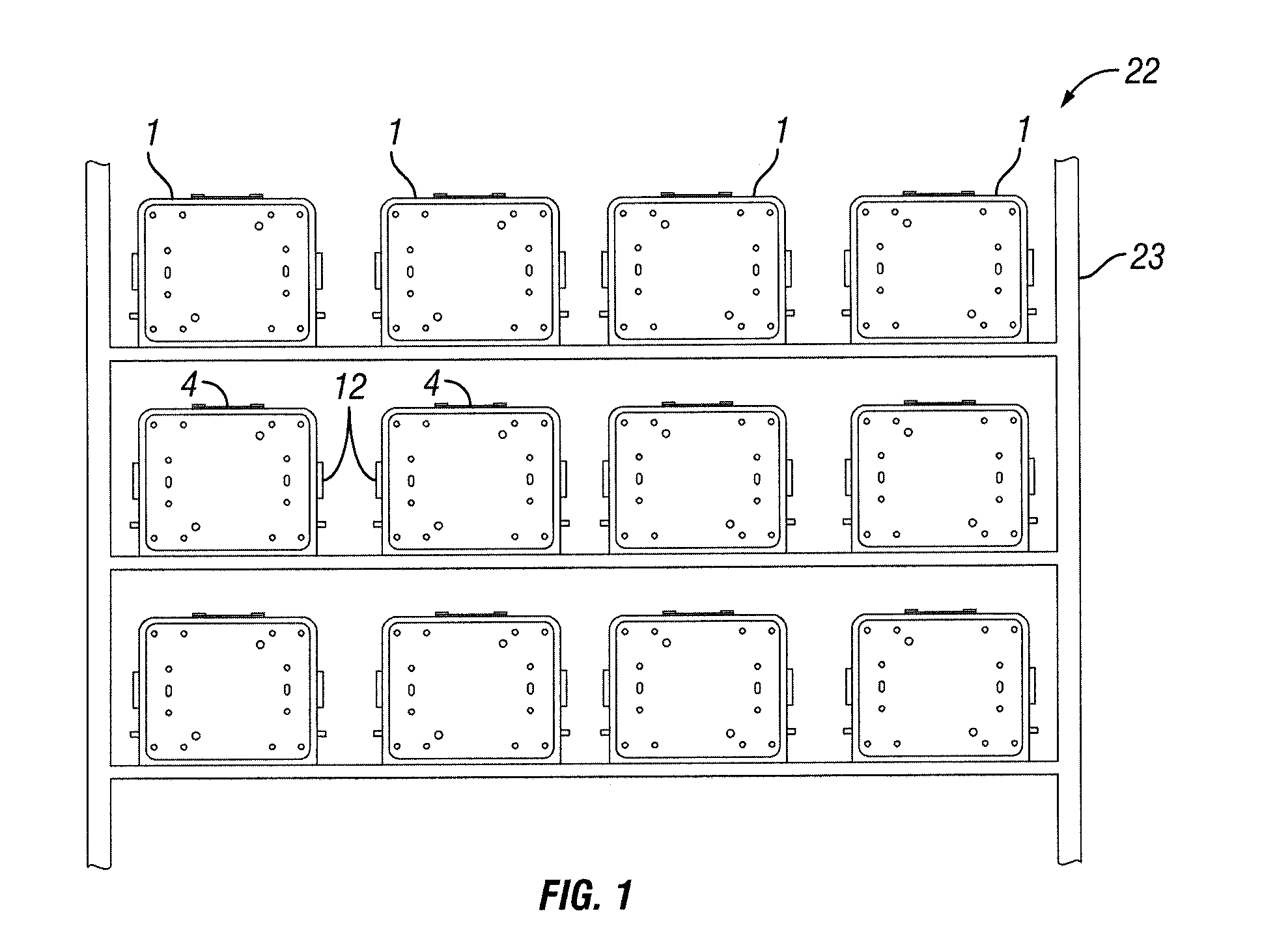
However, due to placement of delivery components such as robotic handles between vertically adjacent wafer storage containers and due to the placement of side handles between horizontally adjacent storage containers, gaps are actually present to allow insertion and removal of the wafer storage containers.
This type of wafer storage container is deficient in that this spreading of the fire causes the adjacent wafer storage containers to burn one after another.

Method used


Image

  • Wafer storage container
  • Wafer storage container
  • Wafer storage container

Examples


example 1

FIG. 4 is Example 1 of a wafer storage container according to an embodiment of the invention. In this example 1, wafer storage container body and support and lid body of the wafer storage container body are formed of PEI having electrical conductivity due to addition of carbon fiber. A window formed of transparent PEI is provided at the backside wall of the container body such that inside of the container body can be seen through the window. The window is integrally formed with the container body by using insert injection molding.

A retainer formed on the inner surface of the lid body and a pair of latch mechanism provided within the lid body is formed of polyether ether ketone which shows excellent abrasion resistance property. Also, the lid cover of the lid is formed of transparent PEI so that operation of the latch mechanism can be seen through the lid cover from outside. Gasket member provided at peripheral edge of the lid body for sealing is formed of fluoro-rubber.

Among the del...

example 2

FIG. 5 is Example 2 of a wafer storage container according to an embodiment of the present invention. Container body and wafer supports and lid body provided with the container body of this example is formed of liquid crystal polymer (LCP) having electrical conductivity due to addition of carbon fiber. In order to provide electrical conductivity, carbon fiber of 10-30 weight parts is added to LCP of 100 weight parts. Surface resistance of this composition can be adjusted to be 103-108 Ω. Other electrically conductive compound such as carbon powder may be added to the carbon fiber in appropriate amount. By forming main part of the wafer storage container by conductive material, adhesion of particles to the wafer storage container can be greatly reduced.

Retainer provided on an inner surface of lid for retaining wafers stored in the container and a pair of latch mechanism stored in the lid body is formed of polyether ether ketone having excellent abrasion resistance property. Also, lid...

example 3

FIG. 6 is Example 3 of a wafer storage container according to an embodiment of the present invention.

Retainer provided on an inner surface of lid for retaining wafers stored in the container and a pair of latch mechanism stored in the lid body is formed of polyether ether ketone_having excellent abrasion resistance property. Also, lid cover provided on the lid main body is formed of transparent PEI such that operation of the latch mechanism within the lid body can be seen through from outside. Gasket member provided on the periphery of lid body is formed of thermoplastic polyester elastomer.

Among the delivery components of the storage container, a robotic flange provided at a top of the container body and a bottom plate provided at a bottom of the container body are formed of PEI having electrical conductivity due to addition of carbon fiber. Optional side rail formed of PEI having electrical conductivity due to addition of carbon fiber is provided at both side walls of the containe...


PUM


Abstract

A wafer storage container including a container body having an opening adapted to store wafers is disclosed. The container body includes a window and wafer support parts. Delivery components are attached to the exterior face part of the container body. The delivery components includes a bottom plate disposed at a bottom of the container body, a pair of side handles disposed at both sides of the container body, and a robotic flange disposed at a top of the container body. The container further is provided with a lid adapted to seal the opening of the container body. The lid includes a lid main body, a pair of latch mechanism disposed within the lid main body, a retainer member disposed at an inner surface of the lid main body, a seal gasket member disposed at a periphery of the lid main body such that it contacts a periphery of an opening part of the container body and a lid cover. The container body, the delivery components and the lid main body are formed of a self-extinguishing material, and the latch mechanism and the retainer member are formed of PEEK, and the gasket member is formed of elastomeric resin.

Description

CROSS-REFERENCE TO RELATED APPLICATIONSThis Application claims priority to Japanese Patent Application No. 2009-233423 filed on Oct. 7, 2009 in Japan.BACKGROUND OF INVENTION1. Field of the InventionThe present invention generally relates to a wafer storage container used for storage, shipping, archiving, or the like of a precision wafer such as a semiconductor wafer.2. Background ArtA wafer storage container for storage of a semiconductor wafer (e.g. precision wafer) is required to allow automatic handling and must have good hermetic sealing in order to prevent contamination of the precision wafer. Synthetic resin material constituting the wafer storage container is selected in order to minimize as much as possible effects of outgassing or elution of ions from the synthetic plastic material. As disclosed by Japanese Unexamined Laid-open Patent Application No. 2000-58633 JP2000-58633, synthetic resins have been used as materials suitable for such a storage container, in which the con...

Claims


Application Information

Patent Timeline
Patent Type & Authority Applications(United States)
IPC IPC(8): B65D85/00
CPCH01L21/67366H01L21/67386H01L21/67373
Inventor KAMADA, TOSHIYUKIMASUKO, HIDEHIRO
Owner SHIN-ETSU POLYMER CO LTD
Learn More