Assembly for detecting more than one rotation through a position encoder magnet

Active Publication Date: 2011-04-07
ASM AUTOMATION SENSORIK MESSTECHN GMBH
View PDF11 Cites 83 Cited by
  • Summary
  • Abstract
  • Description
  • Claims
  • Application Information

AI Technical Summary

Problems solved by technology

This assembly certainly has the disadvantage that small rotation angle changes of the shaft are reflected by the indicator only in a comparatively imprecise manner.
On the one hand side, an increasing number of transmission stages is required for an increasing number of revolutions and the mechanical complexity is increased.
Since typically instead of a simple indicator hand, an angle sensor element is required, which supplies an electrical signal, e.g. the magnetic field sensitive angle sensor element describ

Method used


Image

  • Assembly for detecting more than one rotation through a position encoder magnet
  • Assembly for detecting more than one rotation through a position encoder magnet
  • Assembly for detecting more than one rotation through a position encoder magnet

Examples


first embodiment

[0067]FIG. 1 illustrates an angle sensor according to the invention in an overall view;

[0068]FIG. 2 illustrates an embodiment with a center gear;

[0069]FIG. 3 illustrates a first embodiment with a Ferro-fluidic support;

second embodiment

[0070]FIG. 4 illustrates a second embodiment with Ferro-fluidic support;

[0071]FIG. 5 illustrates an embodiment with a large transmission ratio;

[0072]FIG. 6 illustrates an embodiment with opposed angle sensor elements;

[0073]FIG. 7 illustrates an embodiment with angle sensor elements that are opposed to one another and disposed in several planes;

[0074]FIG. 8 illustrates an embodiment with plural transmission stages;

[0075]FIG. 9 illustrates various embodiments of the particular magnet units;

[0076]FIG. 10 illustrates an embodiment with only one magnet in the magnet unit; and

[0077]FIG. 11 illustrates a specific embodiment of the magnets in the magnet unit.

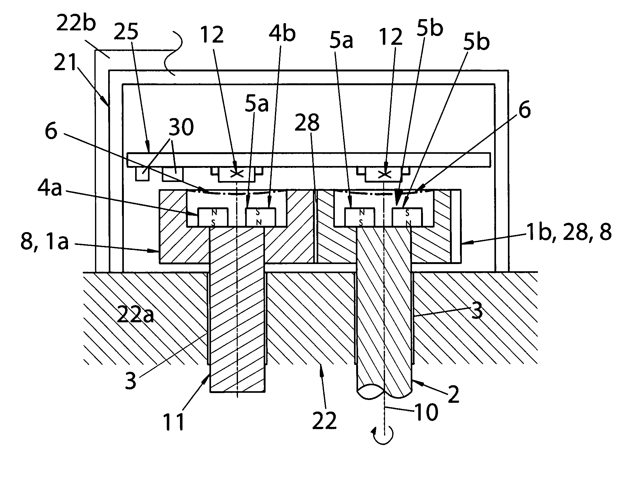
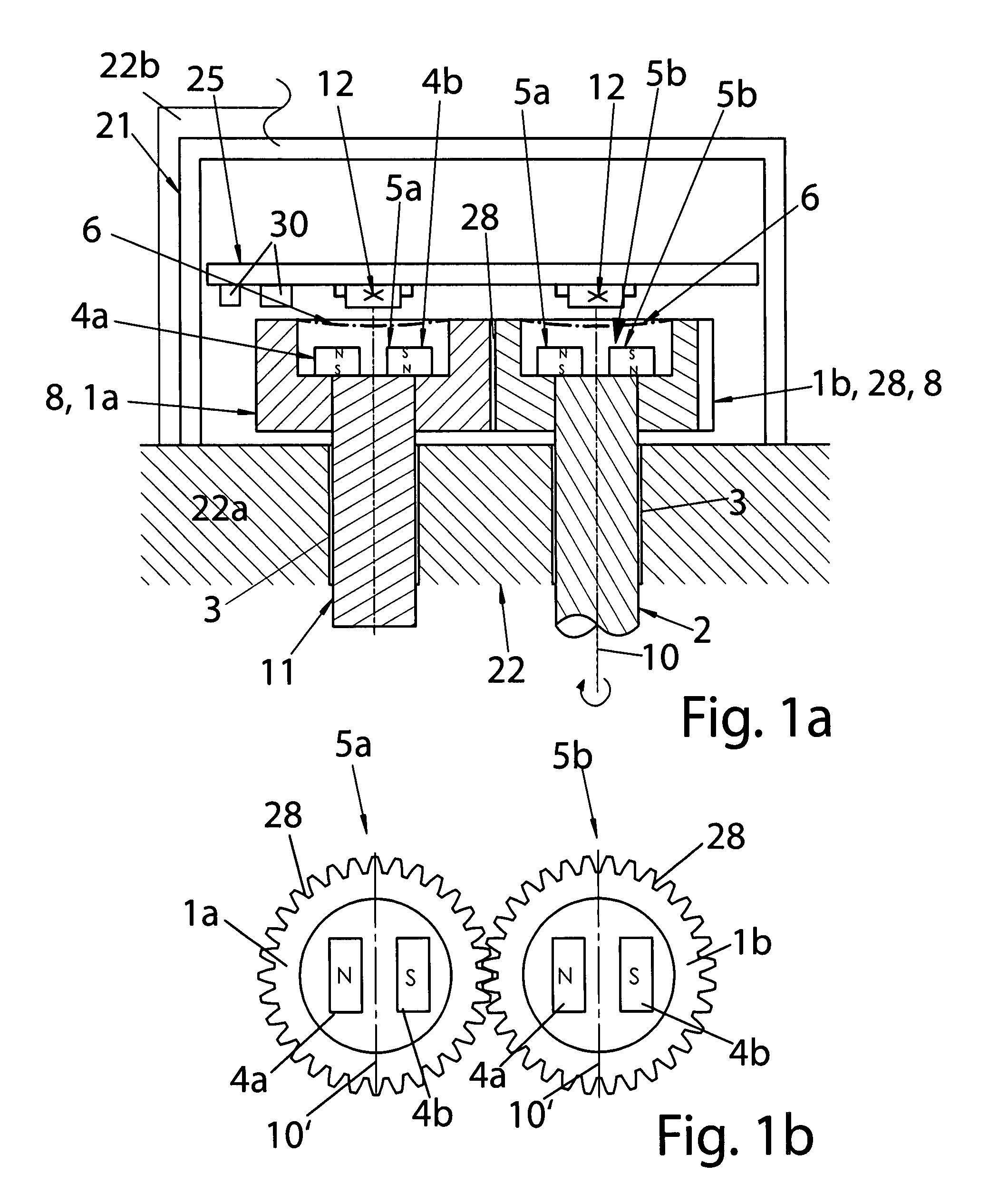
[0078]The angle sensor according to the invention is illustrated in FIG. 1a in a longitudinal sectional view and in FIG. 1b in top view, in which only the two magnet units 5a, b are illustrated.

[0079]Thus, it is apparent that the two gears 1a, b, which are disposed on one, shaft each, mesh with one another, wherein the shaft 2 of the fi...


PUM


Abstract

The rotational position of an encoder magnet can be scanned over more than 360° by respective sensor elements in that magnets are disposed on different stages of a suitable transmission, in particular of a differential transmission, and the magnets are scanned by separate sensor elements, whose signals are computed with one another and yield a total number of revolutions.
In particular, when an assembly of this type shall be built very small, undesirable magnetic interferences for the sensor elements have to be avoided through flux conductor elements since the interferences distort the measurement results. Thus, a differentiation is made between active and passive flux conductor elements.

Description

I. FIELD OF THE INVENTION[0001]The invention relates to a sensor assembly for measuring rotations with more than one full revolution.II. BACKGROUND OF THE INVENTION[0002]In order to indicate a rotation of a body, subsequently generally designated as shaft without limiting the invention thereto, it suffices in the simplest case to use an indicator disposed torque proof at a shaft, wherein the indicator indicates the rotational position.[0003]As soon as the shaft rotates by more than one full revolution, the total amount of rotation cannot be read from such a simple indicator anymore.[0004]An indicator of this type can be mechanically coupled with the shaft, but it can also be coupled touch free, e.g. magnetically coupled.[0005]A typical known solution is disposing a permanent magnet eccentrically on the shaft and detecting its rotational position touch free through a magnetic field sensitive sensor, in particular a multi-Hall assembly.[0006]This multi-Hall assembly, which is typicall...

Claims


Application Information

Patent Timeline
IPC IPC(8): G01B7/30
CPCG01B7/30G01D5/04B62D15/0215G01D5/2452G01D5/145G01D2205/26G01D2205/28
Inventor STEINICH, KLAUS MANFREDWIRTH, PETER
Owner ASM AUTOMATION SENSORIK MESSTECHN GMBH
Why Eureka
Try Eureka