
Powerline network system having data relay function

a powerline network and data relay technology, applied in the field of powerline network systems, can solve the problems of time-consuming and labor-intensive construction, inability to connect any repeater to existing powerlines, and inability to accurately read data,

Inactive Publication Date: 2011-04-07
ACBEL POLYTECH INC
View PDF5 Cites 132 Cited by
  • Summary
  • Abstract
  • Description
  • Claims
  • Application Information

AI Technical Summary

Benefits of technology

[0008]An objective of the present invention is to provide a powerline network communication system ensuring correct transmission and receipt of data and enhancing reliability of communication.
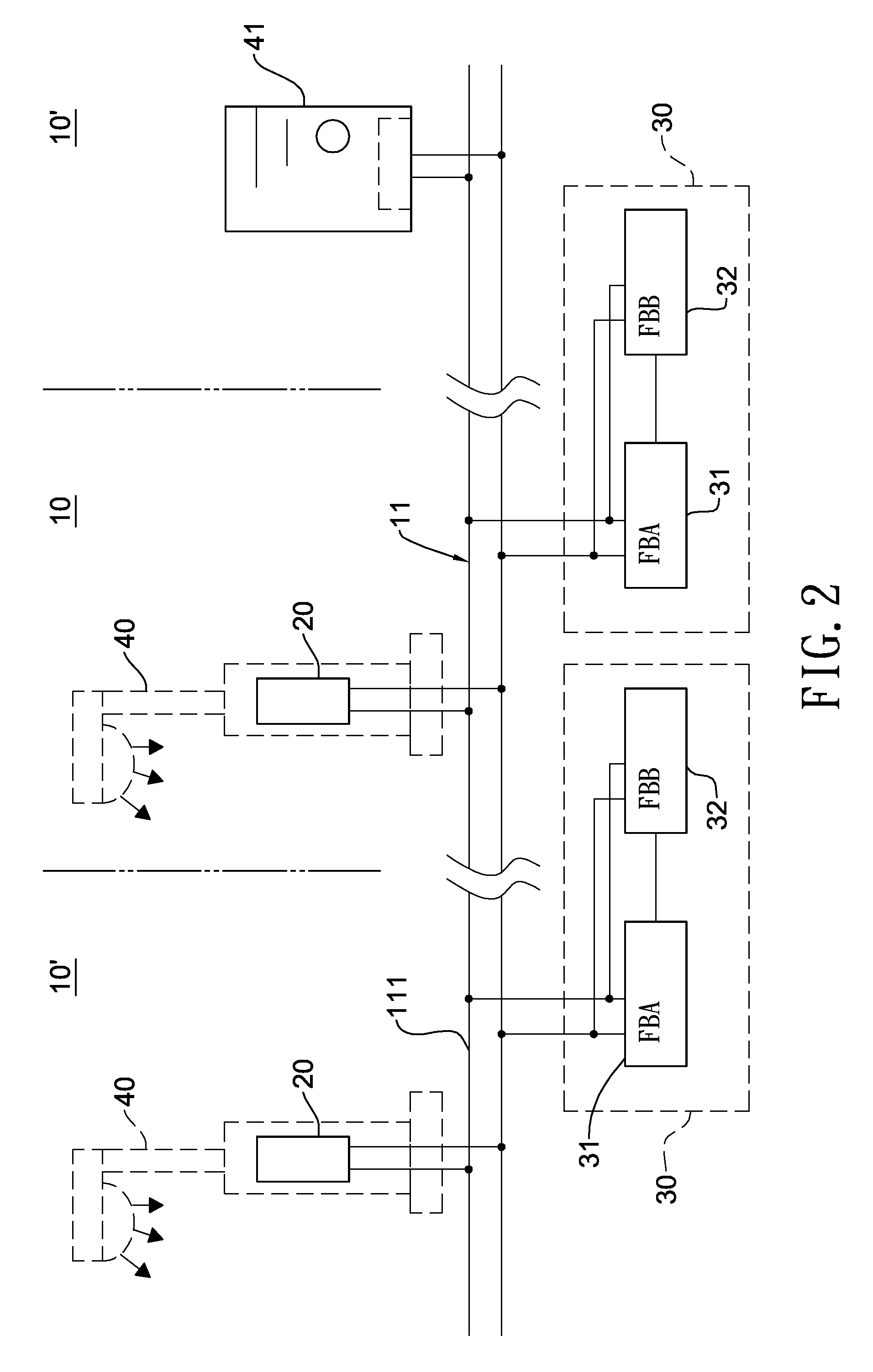
[0014]The repeater of the present invention employs the first relay unit having one modulation frequency and the second relay unit having another modulation frequency to fetch data contained in powerline signals transmitted by each power monitor in adjacent power monitoring zones. The data are received by a relay unit are modulated with different transmitting band and then transmitted to the powerlines of another power monitoring zone. Therefore, it is unnecessary for the repeaters to be serially connected to the powerlines. Not only can the incorrect read issue occurring when data are transmitted over long distance be avoided, but also signal interference of adjacent power monitoring zones is eliminated.

Problems solved by technology

Although powerline network can provide remote surveillance or monitoring using existing powerlines to monitor and control data, transmissions are prone to noise interference.
When a remote site is far from local site, the effective data signal intensity is greatly attenuated, causing incorrect data to be read.
However, serially connecting any repeater to existing powerlines is time-consuming and requires construction investment.
Moreover, electronic components adopted in high-power powerline zone must be high-power electronic components capable of being operated in that environment, thereby increasing entire production cost of the powerline network infrastructure.

Method used


Image

  • Powerline network system having data relay function
  • Powerline network system having data relay function
  • Powerline network system having data relay function

Examples


Embodiment Construction

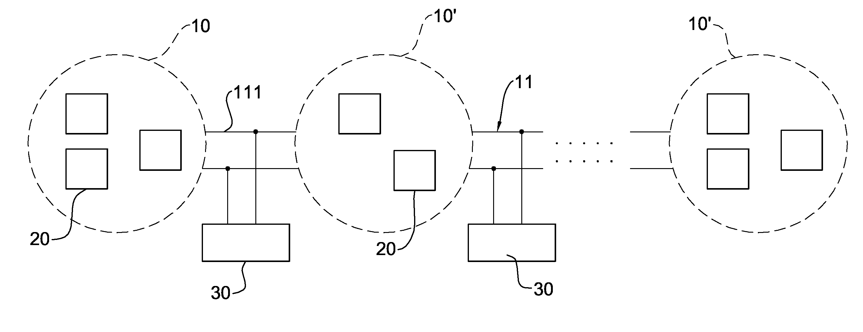
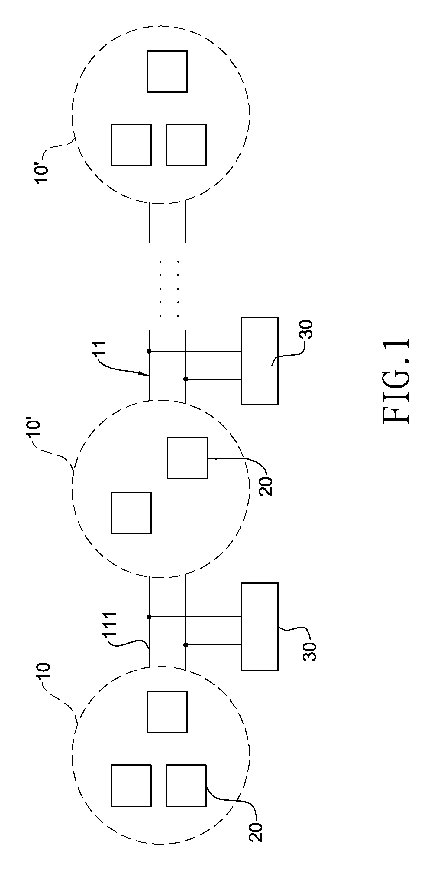
[0019]With reference to FIG. 1, a powerline network system in accordance with the present invention includes a plurality of power monitoring zones (10)(10′) and at least one repeater (30). The plurality of power monitoring zones (10)(10′) are connected with a powerline network (11) to supply the working power. Also, each power monitoring zone (10)(10′) has at least one power monitoring device (20). Each repeater (30) is connected with two adjacent power monitoring zones (10)(10′). In other words, the power monitoring devices (20) in two adjacent power monitoring zones (10)(10′) are mutually connected through powerlines.

[0020]With reference to FIGS. 2 and 3, a preferred embodiment of a powerline network system of the present invention is applied to the power management of street lights. Each repeater (30) has a first relay and a second relay units (31)(32).

[0021]The first relay unit (31) is connected to at least one power monitoring device (20) of a power monitoring zone (10) in neig...


PUM


Abstract

A powerline network system having data relay function includes a plurality of power monitoring zones mutually connected with a powerline network and at least one repeater. Each of the power monitoring zones has at least one power monitoring device. The repeater is connected with each power monitoring device in two adjacent power monitoring zones through powerlines and has a first and a second relay units. The first and second relay units employ two different sets of transmitting and receiving bands to fetch data contained in powerline signals transmitted by each power monitor in adjacent power monitoring zones. The data are received by a relay unit are modulated with different transmitting band and then transmitted to powerlines of another power monitoring zone. The repeaters are not required to be serially connected to the powerlines, and incorrect data read can be also eliminated.

Description

BACKGROUND OF THE INVENTION[0001]1. Field of the Invention[0002]The present invention is related to a powerline network system, and more particularly to a powerline network system correctly transmitting data.[0003]2. Description of the Related Art[0004]The strength of powerline network communication mainly lies in the employment of presently deployed powerlines as the network medium for data transmission without requiring the deployment of additional network lines. Consequently, the expansion of powerline network facilitates the applications in association with widely scattering non-computerized network nodes.[0005]Currently, numerous indoor and outdoor electric appliances embrace the development trend of computerization to provide more and more functions for better operational convenience. In collaboration with the powerline networking technology, remote surveillance or monitoring of the electric appliances, such as, LED street lights embedded with power monitoring function and ene...

Claims


Application Information

Patent Timeline
Patent Type & Authority Applications(United States)
IPC IPC(8): G08C19/16H04L25/20H04L27/00
CPCH04B3/544H04B2203/5445H04B3/58
Inventor CHANG, CHE-CHENGCHIANG, HAO-JANSHIH, CHIH-PIN
Owner ACBEL POLYTECH INC
Learn More