Duplexer and method for separating a transmit signal and a receive signal

a technology of transmit signal and receive signal, which is applied in the direction of transmission, multiple-port network, waveguide type devices, etc., can solve the problem of not able to withstand signals at the transmit power level, and achieve the effect of high performance, low manufacturing cost and high performan

Active Publication Date: 2011-04-07
TELEFON AB LM ERICSSON (PUBL)
View PDF27 Cites 33 Cited by
  • Summary
  • Abstract
  • Description
  • Claims
  • Application Information

AI Technical Summary

Benefits of technology

[0010]The first filtering element and the second filtering element may be of high performance with respect to a precision in filtering, such as a steep roll-off. Typically the first filtering element and the second filtering element are cheap to manufacture but do not withstand signals at the transmit power level. The present disclosure provides the high performance with respect to the precision in filtering of the first filtering element and the second filtering element whilst also allowing the first filtering element and the second filtering element to withstand the transmit power level. The present disclosure further permits usage of the first filtering elements and the second filtering elements having a small footprint even when faced with signals at the transmit power level.
[0011]It is further possible for the analogue quadrature splitter to increase an attenuation of the transmit signal within the at least one receive band. This is of interest when the at least one transmit band and the at least one receive band are closely-spaced or adjacent frequency bands.
[0012]It is to be understood that an increased attenuation of the transmit signal outside the transmit band will help to reduce out-of-band emissions caused by a poor performance of the transmitter or duplexer.

Problems solved by technology

Typically the first filtering element and the second filtering element are cheap to manufacture but do not withstand signals at the transmit power level.

Method used


Image

  • Duplexer and method for separating a transmit signal and a receive signal
  • Duplexer and method for separating a transmit signal and a receive signal
  • Duplexer and method for separating a transmit signal and a receive signal

Examples


Embodiment Construction

[0029]For a better understanding of the present disclosure reference shall now be made to a preferred aspect of the present disclosure, examples of which are illustrated in the accompanying drawings. It will be understood that the embodiments and aspects of the invention described herein are only examples and do not limit the protective scope of the claims in any way. The invention is defined by the claims and their equivalents. It will also be understood that features of one aspect can be combined with features of different aspects.

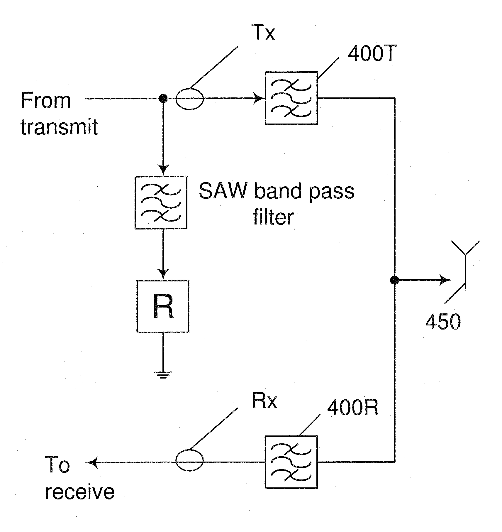
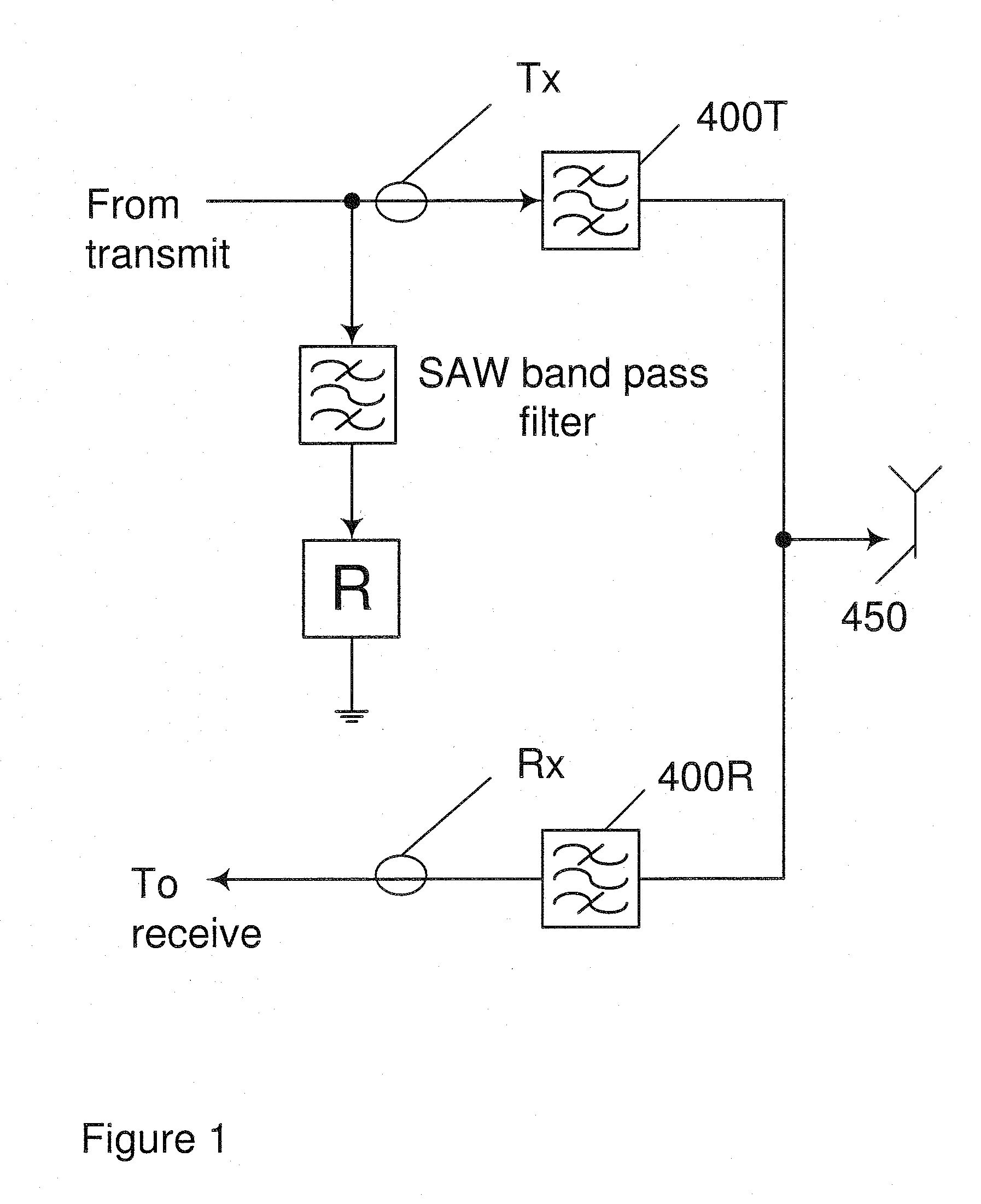
[0030]FIG. 1 shows an example of a duplexer 1a as it is known in the art. The duplexer is used for separating a transmit signal Tx in a transmit band 300Tx and a receive signal Rx in a receive band 300Rx. The duplexer separates two signals in distinct frequency bands. This separation allows the use of the same cable for more than one channel, for example a transmit channel and a receive channel. The duplexer ends at a common antenna 450 as depicted in FI...


PUM


Abstract

The present disclosure provides a duplexer for separating a transmit signal and a receive signal. The duplexer comprises a transmit filter, a receive filter and an analogue quadrature splitter, a first filtering element and a second filtering element. By choosing the first filtering element and the second filtering element substantially identical, it is possible to transform filtering characteristics of the first and second filtering element such that stop bands are substantially transformed into an effective pass band, and vice versa. The analogue quadrature splitter is adapted to increase an attenuation of the transmit signals outside the transmit band, such as in the receive band. Therefore out-of-band emissions by the transmitter will be substantially reduced. The present disclosure further provides a method for separating a transmit signal and a receive signal, and computer program products for the manufacture for carrying out the method of separating transmit signals and receive signals.

Description

CROSS REFERENCE TO OTHER APPLICATIONS[0001]The present application is related to a U.S. patent application entitled: “A Filtering Device and a Method for Filtering a Signal” (Attorney Docket No. 4424-PO4925US0) filed concurrently herewith. The present application is also related to a US patent application entitled: “Filtering Device for Filtering RF Signals and Method for Filtering RF Signals” (Attorney Docket No. 4424-PO4924US0) filed concurrently herewith. The entire disclosure of each of the foregoing applications is incorporated herein by reference.FIELD OF THE INVENTION[0002]The field of the present invention relates to a duplexer for separating a transmit signal and a receive signal using an analogue quadrature splitter to achieve an increased attenuation of the transmit signal outside a transmit band.BACKGROUND OF THE INVENTION[0003]There is a need in the field of radio frequency (RF) technology to provide a duplexer (or duplex filter) for separating a transmit signal Tx and ...

Claims


Application Information

Patent Timeline
Patent Type & Authority Applications(United States)
IPC IPC(8): H04B7/005
CPCH04B1/48
Inventor KENINGTON, PETER
Owner TELEFON AB LM ERICSSON (PUBL)
Why Eureka
Try Eureka