
Multi-Functional Armor System

a multi-functional, armor technology, applied in the field of ballistic armor, can solve the problems of exposing the vehicle to piercing, unable to protect at all from a certain type of projectile, and generally not providing protection against a plurality of types

Inactive Publication Date: 2011-04-14
PLASAN SASA
View PDF19 Cites 3 Cited by
  • Summary
  • Abstract
  • Description
  • Claims
  • Application Information

AI Technical Summary

Benefits of technology

[0005]The present invention is directed to lightweight ballistic armor which can protect against both armor piercing projectiles and high speed fragments resulting from a nearby explosion of an IED or a high energy shell.
[0011]Experiments show that the use of the auxiliary layer made of aluminum alloys as described above allows the armor to stop FSPs of diameters as large as 20 mm having velocities as high as 1500 m / s. This is a surprising effect, since aluminum is known to have relatively low ballistic protection capabilities when used as a frontal material, for which reason it is normally used in internal or backing layers. It is further surprising that commercial and common aeronautical alloys may be used successfully for ballistic protection as suggested in accordance with the present invention, though normally only special armor alloys are used for military applications. While there may be no significant weight difference between military and non-military aluminum alloys, the latter are normally less hard and are cheaper than the former.

Problems solved by technology

Some arrangements of armor will not protect at all against a certain type of projectile.
For example, an array of ceramic tiles or pellets can protect against kinetic energy (KE) threats, such as direct hits of armor-piercing penetrators, while they generally do not provide protection against a plurality, i.e., hundreds, of fragments traveling at a high rate of speed as a consequence of an improvised explosive device (IED) exploding in the vicinity of an armored vehicle.
Typically, the heavy fragmentation impacts resulting from the explosion of an IED destroy the hard, brittle ceramic, exposing the vehicle to be pierced by direct hit shots of sniper rifles or other similar threats.
When performing ballistic tests, it is not practical to explode an IED near an armor prototype.

Method used


Image

  • Multi-Functional Armor System
  • Multi-Functional Armor System

Examples


Embodiment Construction

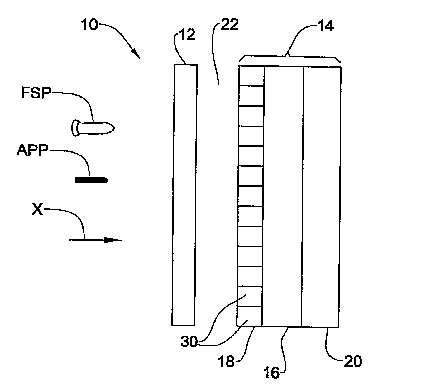
[0016]FIG. 1 is a schematic representation of ballistic armor 10 according to one embodiment of the present invention, adapted to protect a vehicle (not shown) against both a fragment-simulating projectile (FSP) and an armor piercing projectile (APP) traveling in the direction indicated by arrow X.

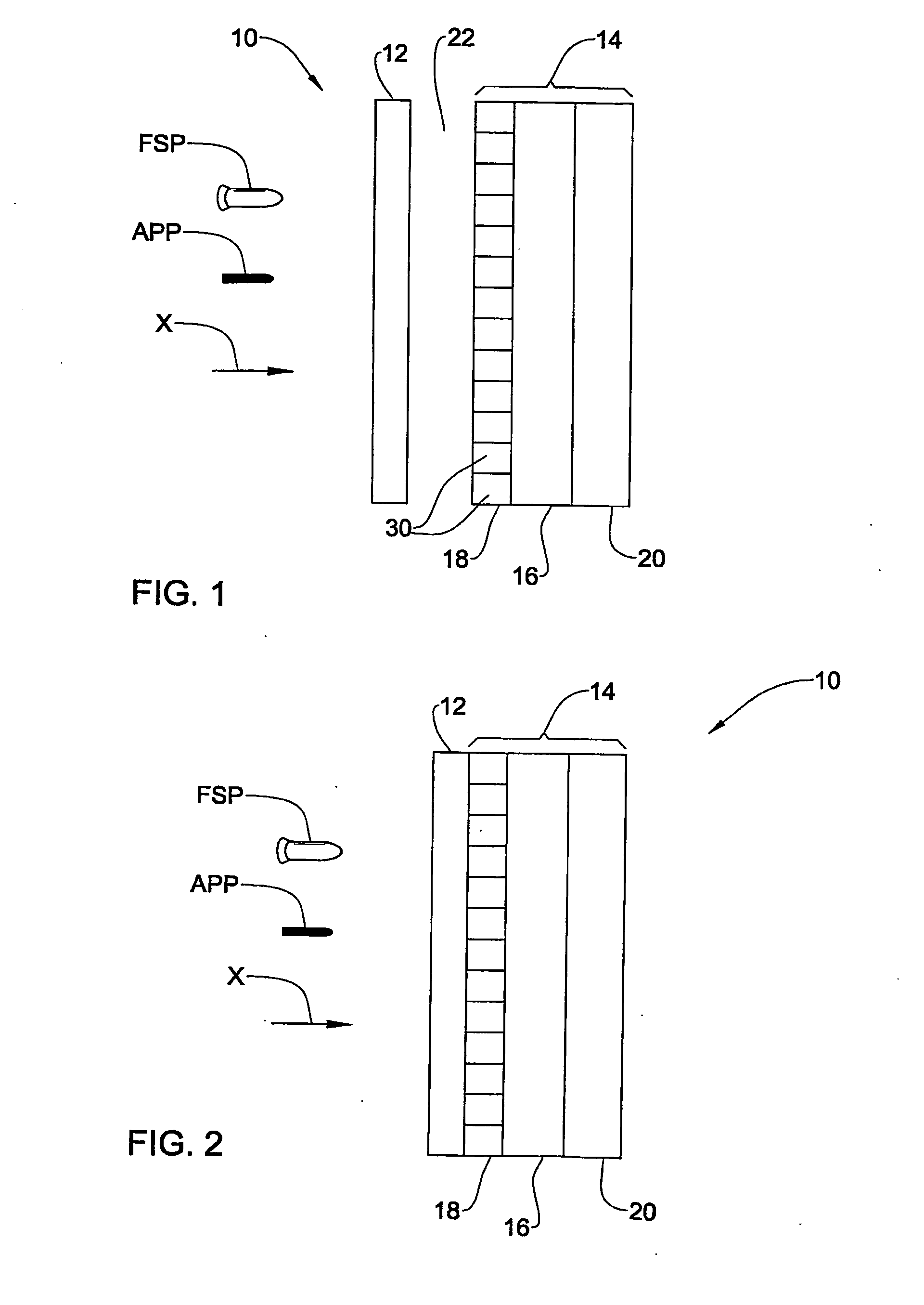
[0017]The armor 10 comprises an auxiliary layer 12 and a main armor layer, which may or may not be separated by a gap 22, as shown in FIGS. 1 and 2.

[0018]The main armor layer 14 comprises a base layer 16, an add-on layer 18 and, optionally, an inner liner 20.

[0019]The base layer 16 is typically made from a hard metallic material such as RHA or high hardness steel which may have a thickness between 4 mm and 20 mm. In the present embodiment, this layer is constituted by the sidewall of the vehicle protected by the armor 10.

[0020]Alternatively, the base layer may comprise dual hardness armor (DHA). For example, such DHA may comprise a layer of UHH steel facing the projectile, and a layer of H...


PUM


Abstract

A ballistic armor adapted to protect against armor piercing projectiles and to withstand multiple impacts of fragment simulating projectiles of a predetermined type, traveling at an initial velocity not exceeding a first velocity. The armor comprises a main armor layer and an auxiliary layer. The main armor layer is adapted to absorb most of the energy of the armor piercing projectiles and to withstand the impacts of the fragment simulating projectiles traveling at a velocity not exceeding a second velocity which is lower than said first velocity. The auxiliary layer is disposed in front of the main armor layer to face the projectiles, and is made of a material which is adapted to undergo a ductile failure mode when perforated by said fragment simulating projectiles and thereby experience localized deformation in the vicinity of each perforation, and which is adapted to cause the fragment simulating projectiles to experience such an energy loss associated with the perforation and deformation as to reduce their velocity from the initial velocity to a velocity not exceeding the second velocity.

Description

FIELD OF THE INVENTION[0001]This invention relates to ballistic armor, particularly those suited to protect against fragmentation.BACKGROUND OF THE INVENTION[0002]When designing ballistic armor, for example, for protecting a vehicle, consideration must be given to the type or types of projectile against which the armor must protect. Some arrangements of armor will not protect at all against a certain type of projectile. For example, an array of ceramic tiles or pellets can protect against kinetic energy (KE) threats, such as direct hits of armor-piercing penetrators, while they generally do not provide protection against a plurality, i.e., hundreds, of fragments traveling at a high rate of speed as a consequence of an improvised explosive device (IED) exploding in the vicinity of an armored vehicle. Typically, the heavy fragmentation impacts resulting from the explosion of an IED destroy the hard, brittle ceramic, exposing the vehicle to be pierced by direct hit shots of sniper rifl...

Claims


Application Information

Patent Timeline
IPC IPC(8): F41H5/04F41H7/02
CPCF41H5/0421F41H5/0492F41H5/045
Inventor RAVID, MOSHEPAK, MARKHIRSCHBERG, YOAV
Owner PLASAN SASA
Learn More