
Device for supplying fuel for an engine and method for mounting a fuel feed line

Inactive Publication Date: 2011-04-14
MAKITA CORP
View PDF11 Cites 4 Cited by
  • Summary
  • Abstract
  • Description
  • Claims
  • Application Information

AI Technical Summary

Benefits of technology

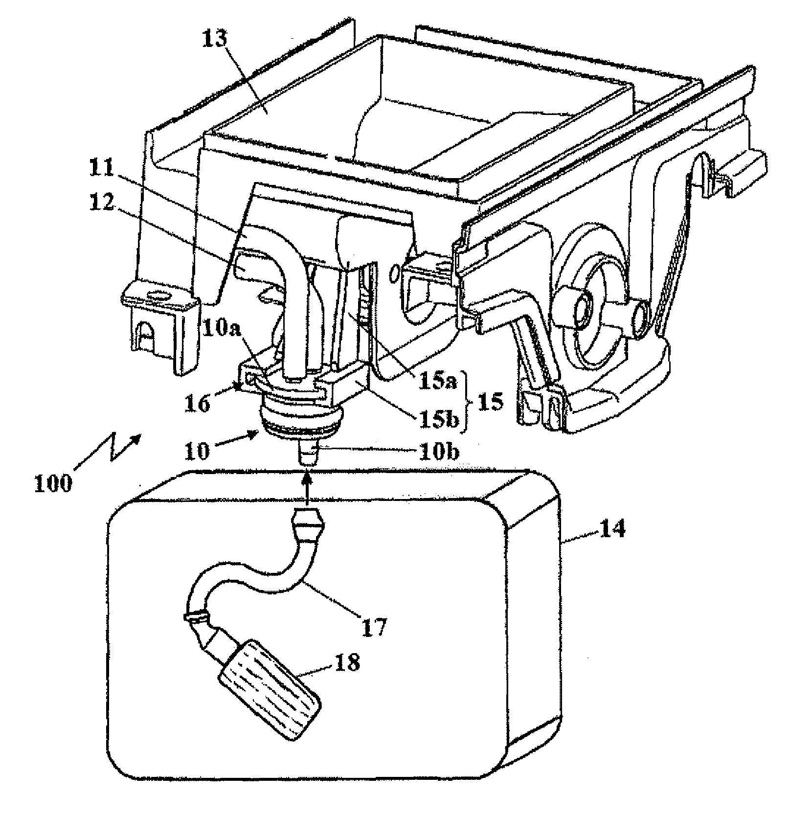
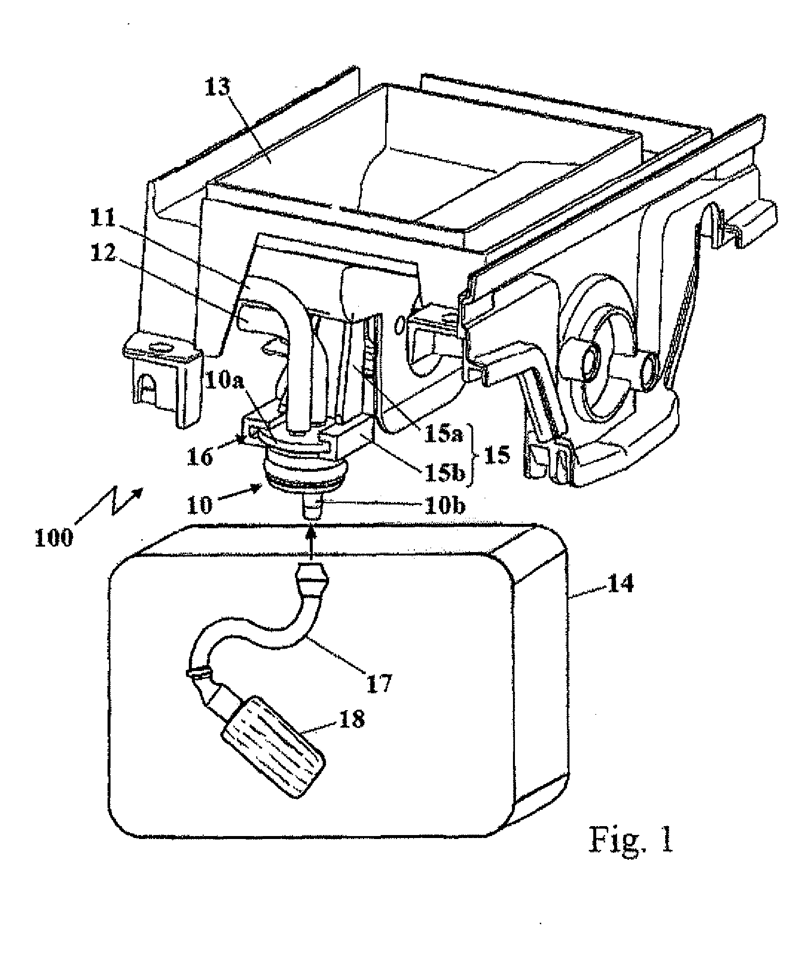
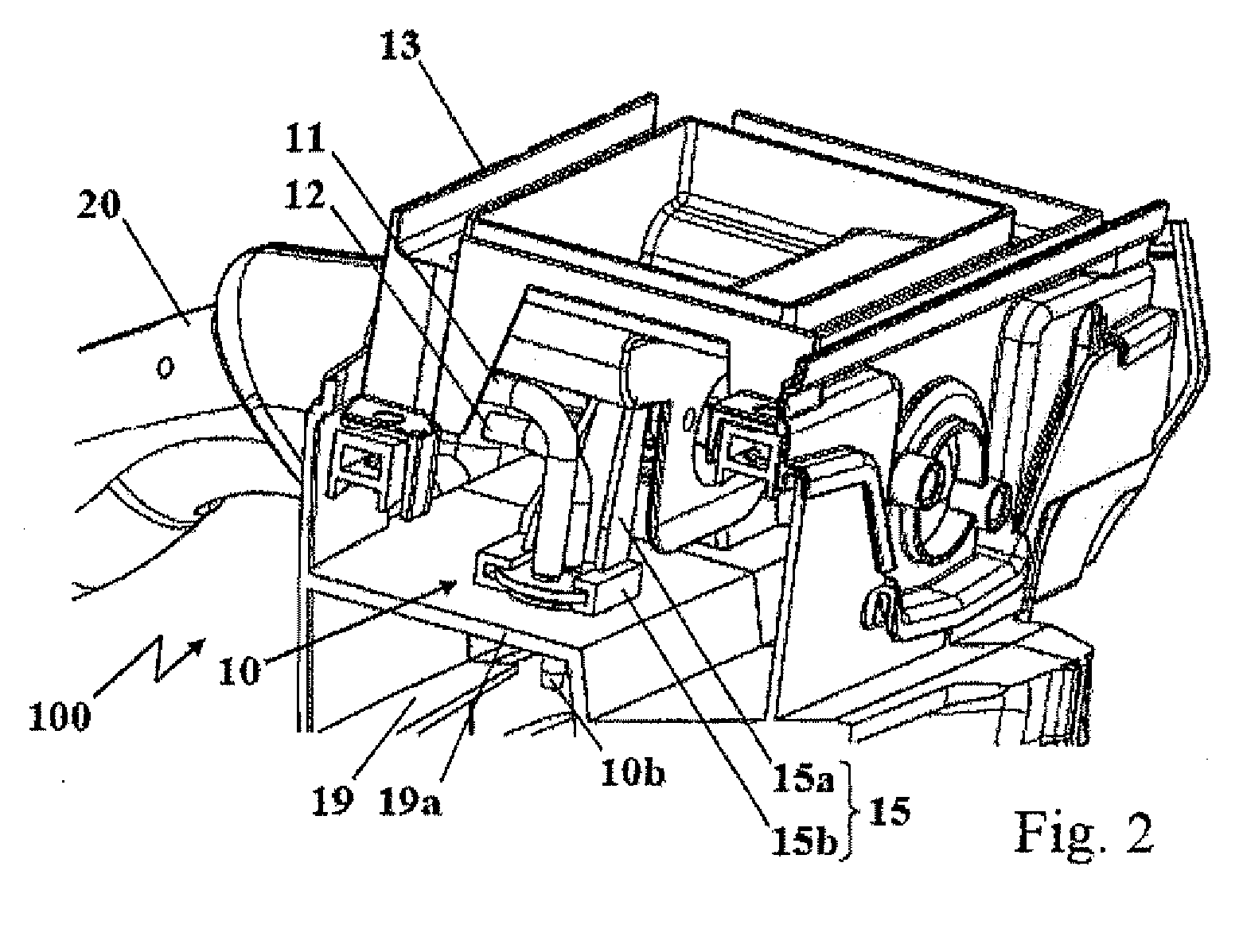
[0006]The arrangement according to the invention of the connecting piece on the intake manifold produces the advantage that an assembly which can be preassembled with intake manifold, connecting piece and fuel lines already connected to the connecting piece is created and provided. This assembly can be supplied as a unit which can be handled individually for assembling the engine or the small piece of equipment. The intake manifold does not just describe a component with the function of introducing charge air. The intake manifold can also be understood as an air filter holding element or as a bridge element for the retentive arrangement of the carburettor unit of the engine, wherein the charge air is conducted through the intake manifold. The intake manifold according to the present invention basically describes any possible component which is mounted adjacently to the fuel tank and can fulfil different functions in order to allow only among other things a retentive arrangement of the connecting piece likewise adjacently to or in the fuel tank according to the invention.
[0008]According to a further advantageous embodiment, the retaining device has a shaft section and a socket section, so that the socket section is arranged at a distance from the intake manifold by means of the shaft section. The socket section is arranged at the end of the shaft section so that the shaft section extends between the intake manifold and the socket section. The shaft section has a defined length in such a manner that, when the intake manifold is arranged adjacently to the fuel tank of the small piece of equipment, a positionally precise arrangement of the connecting piece on or in the fuel tank is made possible.
[0010]The push-in and holding section can advantageously be configured such that the connecting piece can be accommodated in a preferential direction in the guide geometry, The configuration of the push-in and holding section for defining a preferential direction for insertion into the guide geometry can for example have an asymmetry so that the connecting piece can only be introduced into the guide geometry in one direction. The push-in and holding section of the connecting piece can for example have shoulders which form a stop when the connecting piece is pushed far enough into the guide geometry. The shoulders prevent the connecting piece from being inserted into the guide geometry in the wrong direction, and at the same time hoses are prevented from being connected incorrectly to the connecting piece.
[0011]The connecting piece can further advantageously be latched by means of a locking means which is arranged on the connecting piece. This can further facilitate the mounting, as the connecting piece can be arranged in a self-retaining manner in the socket section of the retaining device. The locking means can in particular be integrally formed on the push-in and holding section. Consequently it no longer has to be held manually in the socket section when the device for supplying fuel is mounted. The locking means can be a locking tongue which latches in the manner of a snap hook in a locking opening or behind a locking edge which is introduced in the retaining device.
[0013]It is further advantageous that the connecting piece has at least one tank connector which projects into the fuel tank when the intake manifold, fuel tank and connecting piece on the intake manifold are mounted. The connecting piece, which can also be referred to as a fuel nipple, consequently forms a connection element between a suction line with a suction head and the at least one fuel line. The suction line with the suction head which is present at the end of the suction line is accommodated in the fuel tank itself, The tank connector of the connecting piece projects into the interior of the fuel tank when mounted on the fuel tank, so that the suction line is attached to the tank connector, for example by pushing the suction line onto the tank connector. The suction head has a certain weight to ensure reliable intake of fuel in any working position of the small piece of equipment. The suction line is therefore a flexible hose, for example a silicone hose.

Problems solved by technology

The disadvantage arises that the fuel lines can only be mounted on the connecting piece after the fuel tank with the connecting piece has been inserted.
The connecting piece is often situated in a poorly accessible position on the engine or on the small piece of equipment, as a result of which the process of attaching the fuel line to the connecting piece is time-consuming and complicated.

Method used


Image

  • Device for supplying fuel for an engine and method for mounting a fuel feed line
  • Device for supplying fuel for an engine and method for mounting a fuel feed line
  • Device for supplying fuel for an engine and method for mounting a fuel feed line

Examples


Embodiment Construction

Object, Solution, Advantages

[0003]It is therefore the object of the present invention to create an improved arrangement of a connecting piece of a device for supplying fuel of an engine. It is further the object of the present invention to create an improved method for mounting the device for supplying fuel.

[0004]This object is achieved progressing from a device for supplying fuel for an engine according to Claim 1 and according to Claim 8. Advantageous developments of the invention are specified in the dependent claims.

[0005]The invention includes the technical teaching that the intake manifold has a retaining device for the retentive arrangement of the connecting piece on the intake manifold.

[0006]The arrangement according to the invention of the connecting piece on the intake manifold produces the advantage that an assembly which can be preassembled with intake manifold, connecting piece and fuel lines already connected to the connecting piece is created and provided. This assemb...


PUM

PropertyMeasurementUnit
Distanceaaaaaaaaaa

Abstract

In order to create a device for supplying fuel, with a connecting piece for connecting at least one fuel 1ine of an engine, in particular an engine of a small piece of equipment, for example for garden, forest or landscape maintenance or for example of a motorised tool or the like, wherein an intake manifold is provided which is arranged adjacently to a fuel tank, with an improved arrangement of a connecting piece of a device for supplying fuel of an engine, it is proposed that the intake manifold has a retaining device for the retentive arrangement of the connecting piece on the intake manifold.

Description

[0001]The present invention relates to a device for supplying fuel, with a connecting piece for connecting at least one fuel line of an engine, in particular an engine of a small piece of equipment, for example for garden, forest or landscape maintenance or for example of a motorised tool or the like, wherein an intake manifold is provided which is arranged adjacently to a fuel tank.PRIOR ART[0002]DE 10 2007 029 617 A1 discloses a generic device for supplying fuel, with a connecting piece for connecting at least one fuel line of an engine. The connecting piece is inserted in the fuel tank of the engine and built in together with it. The disadvantage arises that the fuel lines can only be mounted on the connecting piece after the fuel tank with the connecting piece has been inserted. The connecting piece is often situated in a poorly accessible position on the engine or on the small piece of equipment, as a result of which the process of attaching the fuel line to the connecting piec...

Claims


Application Information

Patent Timeline
IPC IPC(8): F02M35/10B23P11/00
CPCF02M37/007F02M37/0047Y10T137/6855Y10T137/0402
Inventor SCHOLZ, KLAUS
Owner MAKITA CORP
Learn More