Standard cell arrangement for a magneto-resistive component

Inactive Publication Date: 2005-05-17
SIEMENS AG
View PDF6 Cites 3 Cited by
  • Summary
  • Abstract
  • Description
  • Claims
  • Application Information

AI Technical Summary

Benefits of technology

[0010]In a development of the concept of the invention, it may be provided that provision is made of a plurality of symmetrically constructed cells for forming an enlarged standard cell arrangement with an area of the magnitude ‘1’ which corresponds to an integer multiple of the area of the rectangular basic form of the single cell. In the case of this refinement of the invention, the invention proposes not only defining a single standard cell but also enlarged standard cell arrangements corresponding to a multiple of a single cell, that is to say for example to double or triple the latter, a corresponding number of magnetic layer systems and also inputs and outputs then also being provided here. The corresponding dimensioning of the magnitude of this enlarged standard ce

Problems solved by technology

Since magnetoresistive components are increasingly gaining in importance, such a p

Method used


Image

  • Standard cell arrangement for a magneto-resistive component
  • Standard cell arrangement for a magneto-resistive component
  • Standard cell arrangement for a magneto-resistive component

Examples


first embodiment

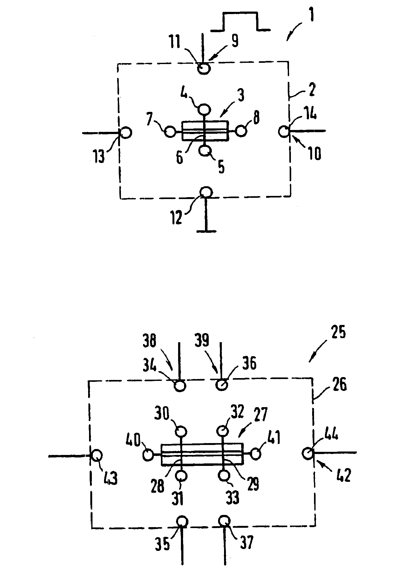
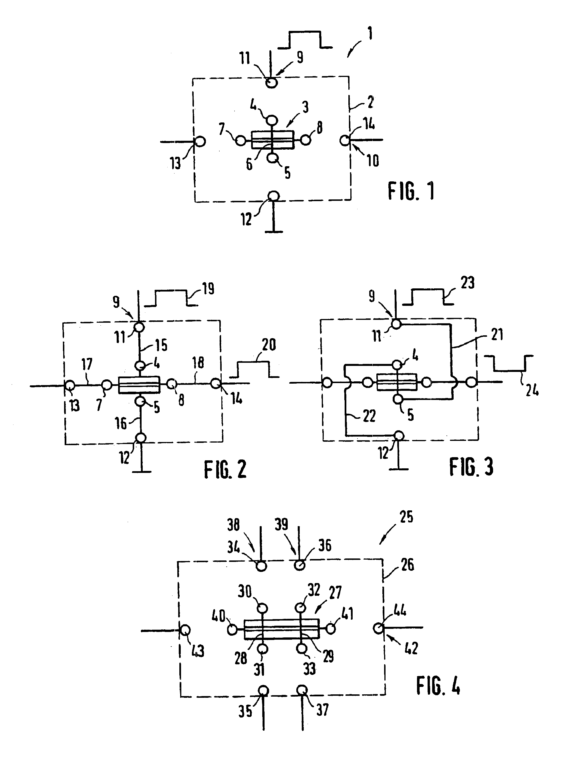
[0026]FIG. 1 shows a standard cell arrangement 1 of a first embodiment in the form of a schematic sketch. The standard cell arrangement has an essentially rectangular basic form 2, as is indicated by the dashed line. Furthermore, a magnetoresistive layer system3, which is only represented in principle here, is provided in the cell center. The layer system may be a GMR system (giant magnetoresistive), TMR system (tunnel magnetoresistive), AMR system (anisotropy magnetoresistive) or a CMR system (colossal magnetoresistive). The layer system 3 or assigned to the latter are system input terminals 4, 5, which are connected to one another via an interconnect 6. A current is carried via said terminals 4, 5 or the interconnect 6 during operation, which current generates a magnetic field which acts on the magnetoresistive layer system 3 and, depending on the design thereof, if appropriate brings about magnetization reversal effects. The basic principle of such a magnetoresistive layer system...

second embodiment

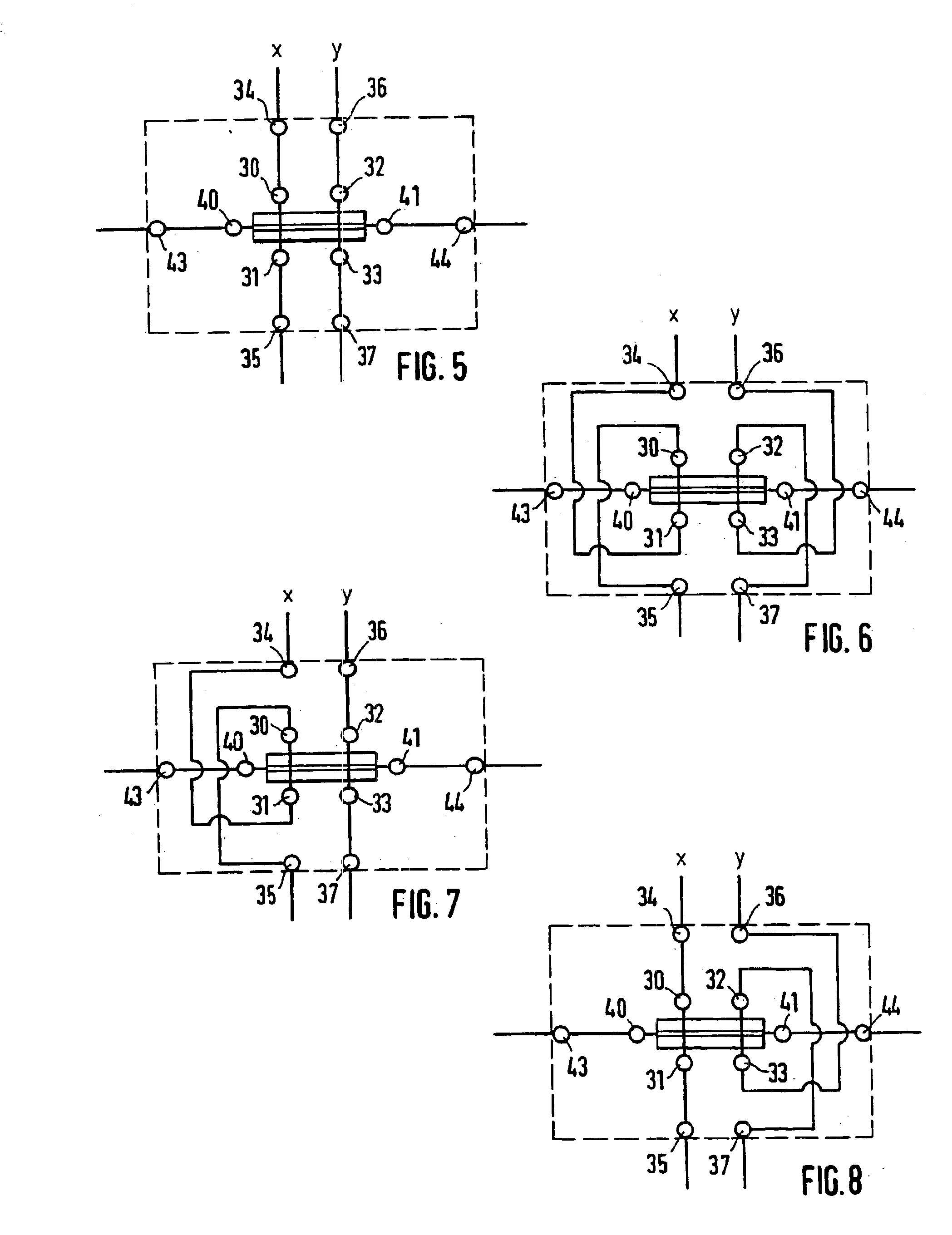
[0034]FIG. 4 shows a standard cell arrangement 25 according to the invention. This standard cell arrangement likewise has a rectangular basic form 26, represented by the dashed line, and a magnetoresistive layer system 27 is provided in the cell center. In the case of this layout, said layer system is assigned two interconnects 28, 29 with respective system input terminals 30, 31 and 32, 33, which are assigned directly opposite input terminals 34, 35 and 36, 37, respectively, which are provided at the cell periphery and altogether form two inputs 38, 39. It is thus possible to apply two separate current pulses and thus input signals to the layer system or to generate corresponding magnetic fields, with the result that logic gates can be constructed with this configuration.

[0035]Furthermore, two system output terminals 40, 41 are provided, which are assigned peripheral output terminals 43, 44 forming an output 42.

[0036]It should already be pointed out at this juncture that there is n...


PUM


Abstract

A standard cell arrangement for a magneto-resistive component, comprising at least one magneto-resistive layer system, preferably in the center of the cell, in addition to at least one input and at least one output on the cell periphery. The input is provided with two input connections which can be connected to each other in order to conduct a current producing a magnetic field used to influence the magneto-resistive layer system. The output has two output connections which can be connected to the magneto-resistive layer system to pick off a signal. The input and output connections are arranged at predetermined points in relation to a rectangular basic shape of said cell (respectively mirror-symmetrical or point-symmetrical to the center of the cell).

Description

CROSS REFERENCE TO RELATED APPLICATIONS[0001]This is the 35 USC 371 national stage of international application PCT / DE02 / 03146 filed on Aug. 28, 2002, which designated the United States of America.FIELD OF THE INVENTION[0002]The invention relates to a standard cell arrangement for a magnetoresistive component, in particular a logic component.BACKGROUND OF THE INVENTION[0003]A magnetoresistive component comprising at least one magnetoresistive layer system with the associated inputs and outputs has hitherto been planned individually, that is to say the component has an individual architecture. In this case, the circuit layout (wiring, positioning) is usually designed manually or using self-created layout software. Since magnetoresistive components are increasingly gaining in importance, such a procedure for the configuration of the layout or the architecture is not expedient.SUMMARY OF THE INVENTION[0004]In this case, the invention is based on the problem of specifying a possibility ...

Claims


Application Information

Patent Timeline
IPC IPC(8): H03K19/02H03K19/18H01L43/08H03K19/20
CPCH03K19/18
Inventor BANGERT, JOACHIM
Owner SIEMENS AG
Why Eureka
Try Eureka