
Arrangement and method for performing chromatography

a chromatography and arrangement method technology, applied in the field of arrangement and method for performing chromatography, can solve the problems of limited separation efficiency by tlc, limited use of glass columns, and high cost of hplc systems designed for preparative chromatography techniques, etc., to achieve efficient separation of mixture components, short development time, and improved arrangement and method

Inactive Publication Date: 2007-10-09
INDIANA UNIV RES & TECH CORP
View PDF11 Cites 5 Cited by
  • Summary
  • Abstract
  • Description
  • Claims
  • Application Information

AI Technical Summary

Benefits of technology

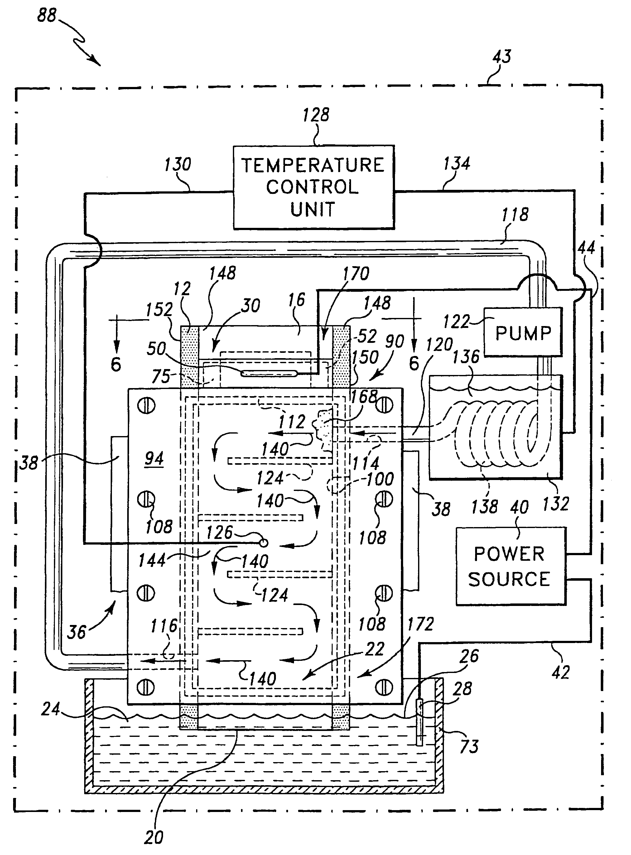
[0012]Pursuant to another embodiment of the present invention there is provided a method of performing chromatography with a chromatographic bed having a stationary phase. The method includes the steps of (a) positioning the chromatographic bed and the stationary phase within a sealed cavity, (b) placing the stationary phase in contact with a liquid mobile phase while the stationary phase is positioned within the sealed cavity, (c) advancing a fluid into the sealed cavity so that pressure within the sealed cavity is greater than the pressure outside of the sealed cavity, (d) placing a first electrode in contact with the liquid mobile phase, (e) placing a second electrode in contact with the stationary phase, and (f) creating an electrical potential between the first and second electrode so as to cause the liquid mobile phase to be advanced through the chromatographic bed positioned within the sealed cavity.
[0020]It is yet another objective of the present invention to have the mobile phase at optimum velocity for maximum chromatographic efficiency.

Problems solved by technology

For example, (i) HPLC system can only separate one mixture at a time, (ii) HPLC systems require special pumps and inlet devices to respectively generate and accommodate the high pressures required to perform HPLC, (iii) HPLC columns must be constructed from mechanically strong materials which limits the use of glass columns that are particularly useful for handling many biological samples, (iv) HPLC systems designed for preparative chromatography techniques are very expensive, and (v) detector dead volumes must be keep extremely small (several microlitres) in order to avoid additional band spreading.
However, like HPLC, TLC also suffers from several significant disadvantages.
In particular, the separation efficiency by TLC is limited by the inadequate mobile phase flow under capillary action.
This capillary-induced mobile phase flow is neither fast enough nor constant throughout the chromatographic run, and both of these drawbacks tend to decrease the separation efficiency of TLC substantially.
Moreover, the relatively slow movement of the mobile phase results in rather long development times.
OPLC also suffers from significant drawbacks.
Having the migration characteristics of the mobile phase sensitive to the particle size and the particle size distribution of the stationary phase can decrease the separation efficiency of OPLC.

Method used


Image

  • Arrangement and method for performing chromatography
  • Arrangement and method for performing chromatography
  • Arrangement and method for performing chromatography

Examples


Embodiment Construction

[0035]While the invention is susceptible to various modifications and alternative forms, a specific embodiment thereof has been shown by way of example in the drawings and will herein be described in detail. It should be understood, however, that there is no intent to limit the invention to the particular form disclosed, but on the contrary, the intention is to cover all modifications; equivalents, and alternatives falling within the spirit and scope of the invention as defined by the appended claims.

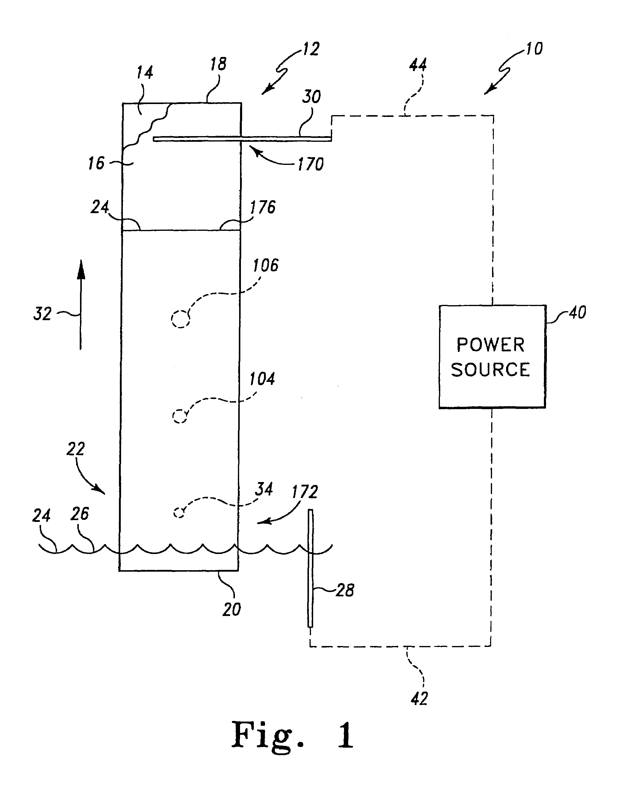
[0036]Referring to FIG. 1 there is shown a chromatography arrangement 10 which incorporates certain features of the present invention therein. Arrangement 10 includes a thin layer chromatography plate 12 (hereinafter referred to as plate 12), an electrical power source 40, a first electrode 28 such as an anode, and a second electrode 30 such as a cathode. Arrangement 10 also includes a mobile phase 24 and a pair of electrical wires 42 and 44. Hereinafter first electrode 28 will be refer...


PUM

PropertyMeasurementUnit
electrical potentialaaaaaaaaaa
v/vaaaaaaaaaa
particle sizeaaaaaaaaaa

Abstract

An arrangement for performing chromatography with a mobile phase and a chromatographic bed having a stationary phase is provided. The arrangement includes a support assembly configured to support the stationary phase. The support assembly has a sealed cavity configured so that when the support assembly is supporting the stationary phase a portion of the chromatographic bed and the stationary phase extends into the sealed cavity. The arrangement further includes a bladder having a void defined therein. The bladder is positioned within the sealed cavity. The arrangement also includes a fluid positioned within the void of the bladder so that the bladder is urged toward the stationary phase within the sealed cavity. The arrangement further includes an anode positioned in contact with the mobile phase. The arrangement also includes a cathode positioned in contact with the stationary phase, wherein creating an electrical potential between the anode and the cathode causes the mobile phase to be advanced through the chromatographic bed positioned within the sealed cavity. An associated method is also provided.

Description

CROSS REFERENCE TO RELATED APPLICATIONS[0001]The present application is a division of U.S. patent application Ser. No. 09 / 941,205, filed on Aug. 28, 2001 now U.S. Pat. No. 6,610,202, which is a continuation of U.S. patent application Ser. No. 09 / 426,297, filed on Oct. 25, 1999, now U.S. Pat. No. 6,303,029.BACKGROUND OF THE INVENTION[0002]The present invention generally relates to an arrangement and method for performing chromatography. The present invention particularly relates to an arrangement and method for performing chromatography utilizing electroosmotic flow of a mobile phase.[0003]Multiple techniques have been developed which enable the separation of complex mixtures into their components. Chromatography is one such technique. Chromatography can be described as a separation process based on differences in the rate at which the components of a mixture move through a chromatographic bed under the influence of a mobile phase which moves relative to a chromatographic bed. The ch...

Claims


Application Information

Patent Timeline
Patent Type & Authority Patents(United States)
IPC IPC(8): B01D15/08G01N30/28G01N30/30G01N30/90G01N30/92G01N30/94
CPCG01N30/90G01N30/94G01N30/92G01N2030/285G01N2030/3007G01N2030/906G01N30/6047
Inventor NUROK, DAVIDFROST, MEGAN
Owner INDIANA UNIV RES & TECH CORP
Learn More