Wind turbine rotor

a wind turbine and rotor blade technology, applied in the field of wind turbine rotors, can solve the problems of affecting the development of larger installations, and affecting the placement of structures in the landscape,

Inactive Publication Date: 2013-06-18
HOLMOY VIDAR
View PDF15 Cites 2 Cited by
  • Summary
  • Abstract
  • Description
  • Claims
  • Application Information

AI Technical Summary

Benefits of technology

[0029]Some positive effects of the invention may be summarized as follows:[0030]A stronger, slimmer and lighter construction. Approximately 30-40% reduction in material and building costs even with an increase in number of rotor blades from 3 to 4. Reduced stress in the rotor blade and in the mounting towards the rotor shaft. Prospects of simple joints which do not have to transfer large bending forces.[0031]Considerably stiffer rotor blades. This facilitates larger clearing between tower and rotor blade tips and thereby space for designing towers with three or four legs which are stiffer, lighter, taller and more cost efficient than the current mono columns. Remember that the traditional columns give considerable movements (“seaway”) in the tower under operation.[0032]Handling is simplified and manufacturing and transport cost are reduced. The parts are getting shorter, and possibly even more important: the rotor blades are getting slimmer. Transport under bridges and on normal roads is facilitated. Considerably larger turbines may simply be built on land. Economically optimal size increases from 2-3 MW to approximately 12 MW.[0033]Prospects of building wind turbines with considerably larger rotor radius than today. Considerable positive consequences for the extent of renewable energy.[0034]Smaller bending forces and thereby easier turning of the rotor blade. Makes pitch control of the rotor blades likely with less powerful equipment. This may possibly take place more rapidly and thereby reduce large forces within rotor blade and rotor.[0035]Prospects of improved architecture and arrangement of the wind power plants.
[0030]A stronger, slimmer and lighter construction. Approximately 30-40% reduction in material and building costs even with an increase in number of rotor blades from 3 to 4. Reduced stress in the rotor blade and in the mounting towards the rotor shaft. Prospects of simple joints which do not have to transfer large bending forces.
[0031]Considerably stiffer rotor blades. This facilitates larger clearing between tower and rotor blade tips and thereby space for designing towers with three or four legs which are stiffer, lighter, taller and more cost efficient than the current mono columns. Remember that the traditional columns give considerable movements (“seaway”) in the tower under operation.
[0032]Handling is simplified and manufacturing and transport cost are reduced. The parts are getting shorter, and possibly even more important: the rotor blades are getting slimmer. Transport under bridges and on normal roads is facilitated. Considerably larger turbines may simply be built on land. Economically optimal size increases from 2-3 MW to approximately 12 MW.
[0033]Prospects of building wind turbines with considerably larger rotor radius than today. Considerable positive consequences for the extent of renewable energy.
[0034]Smaller bending forces and thereby easier turning of the rotor blade. Makes pitch control of the rotor blades likely with less powerful equipment. This may possibly take place more rapidly and thereby reduce large forces within rotor blade and rotor.

Problems solved by technology

From this it may be understood that the rotor blades get relatively thicker, broader, heavier and more expensive.
This hinders the development towards larger installations.
These are produced and transported in whole lengths, which evidently constitutes an increasing challenge when the line of business talks about rotor blades of 100 meters in a few years.
When the rotor diameter increases, the same rotation frequency will cause the speed furthest out to surpass 60-70 m / s, and noise problems will arise making the structures unfavourable for placement in the landscape.
This solution reduces the deflection forces in the rotor blade, but is not practical because the backstays closest to the tower are in the way making it very difficult to mount the rotor without it touching the tower.
The list below presents problems with solutions according to prior art:Bending forces and deflection of the rotor blades during use causes fatigue and may additionally result in lack of distance to the tower structure.Therefore the tower structure normally is designed as a large, conical tube.
The material cost and the concept are however unsuitable for large sizes.Lack of stiffening causes fatigue stress on the materials which limits the lifetime of blades and tower and more.The length of the blades must be limited because the rotor blades get heavy if they are to be sufficiently stiff.
This in turn causes earlier fatigue due to the gravitational forces.
All this makes large rotor radiuses very expensive and unsuitable compared to the gains which may be achieved.Turning of the rotor blades around the longitudinal axis is necessary for optimal control of the angle of the rotor blades under normal operation, and for “position of rest” for example by heavy wind.
Eventual rotor stiffening elements makes this difficult and these are virtually not in use today.Long rotor blades are difficult to transport.The stiffening elements causes increased noise from the wind power plant rotor and restrain rotation because of air drag.

Method used


Image

  • Wind turbine rotor
  • Wind turbine rotor
  • Wind turbine rotor

Examples


Embodiment Construction

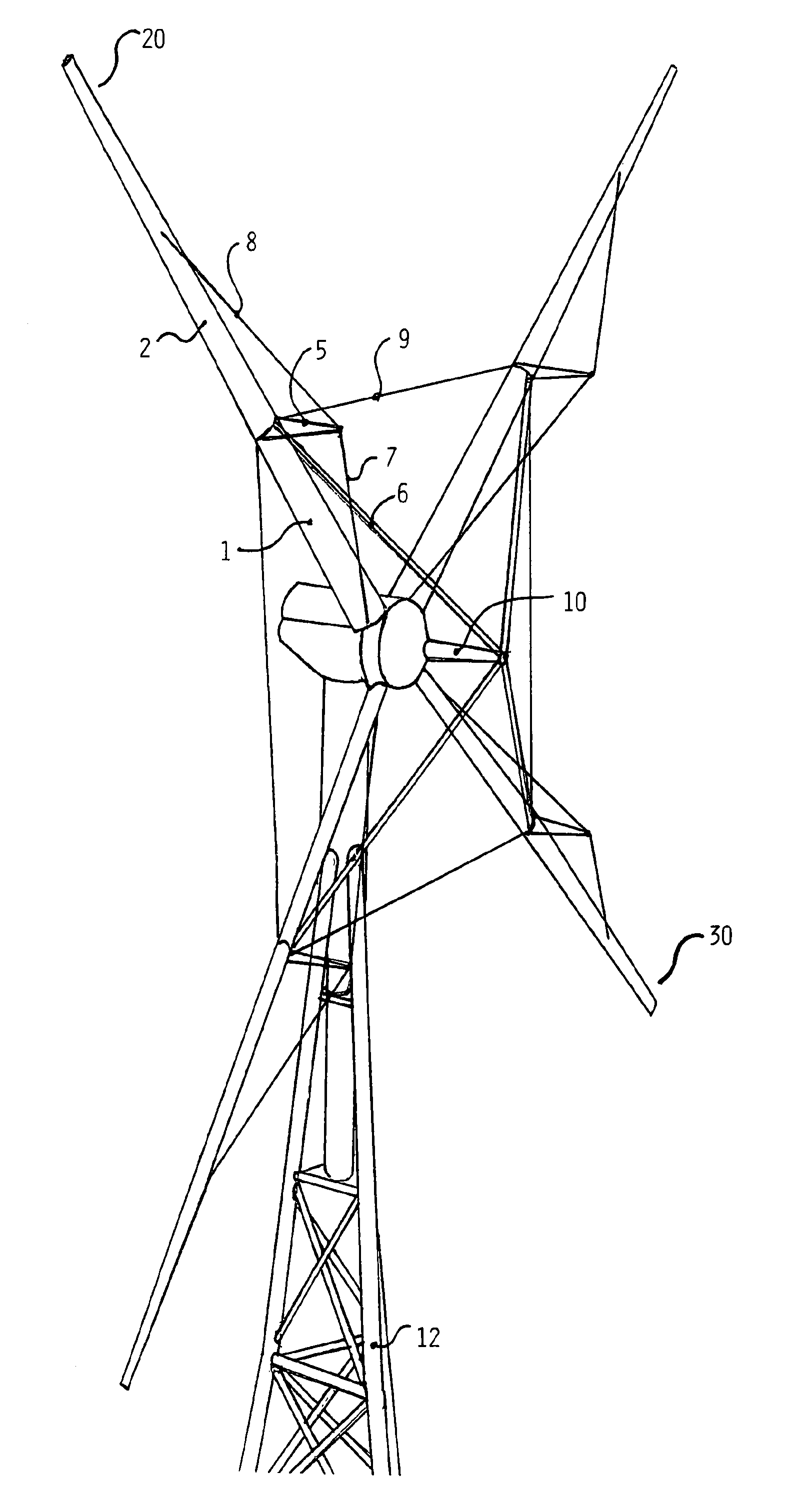
[0042]An embodiment example of a wind power plant rotor with two-piece rotor blades (20, 30) according to the invention is described with reference to the figures.

[0043]FIG. 1 presents a wind mill with tower (12) and wind power plant rotor according to the invention. The wind power plant rotor comprises a rotor shaft (10), four rotor blades (20, 30) each of which comprises two rotor blade parts (1, 2), and a number of stiffening elements (5-9) including radial blade stiffening elements (7 and 8) and tangential rotor stiffening elements or ring stiffening (9), and rotor shaft strut.

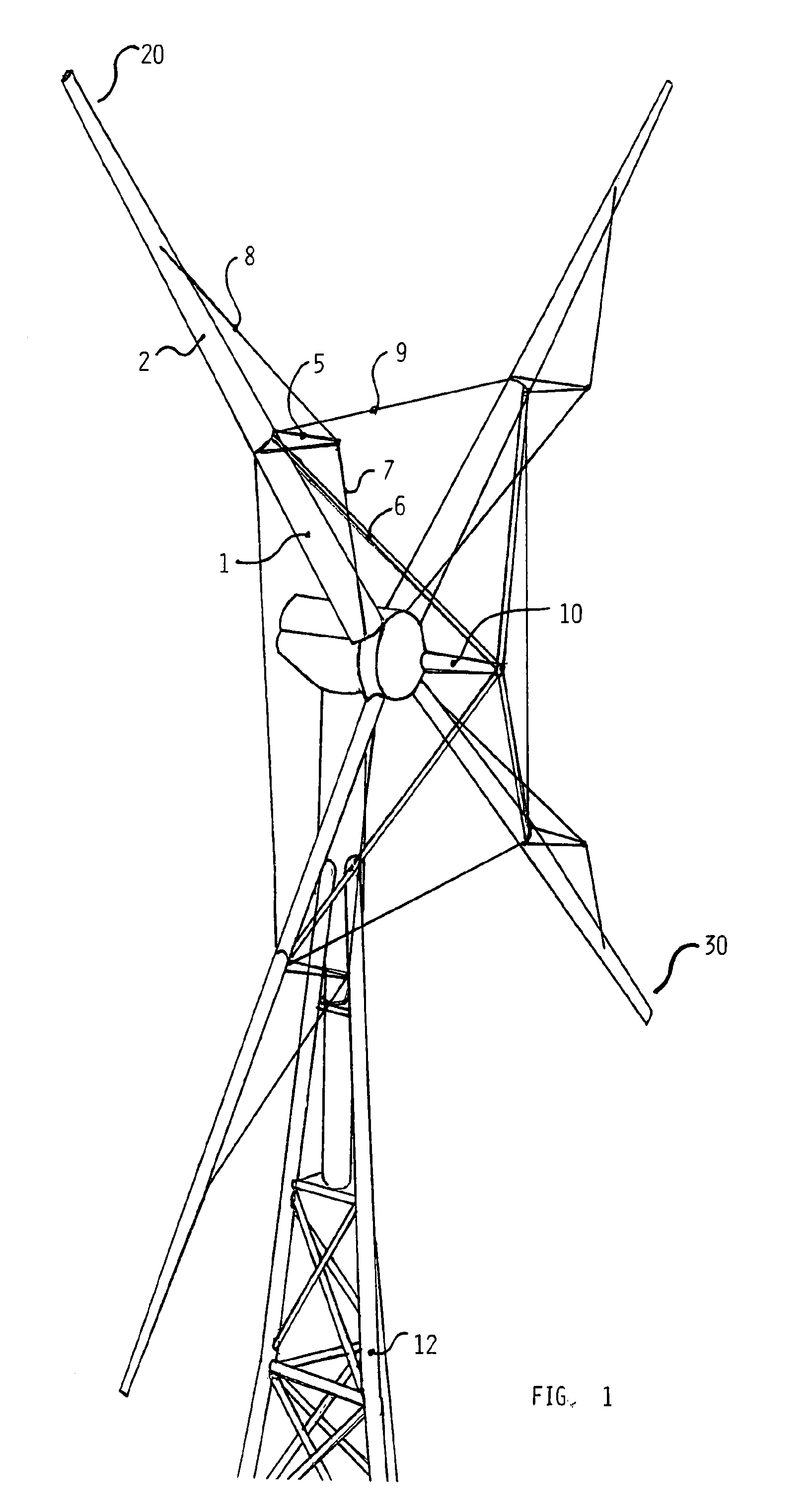
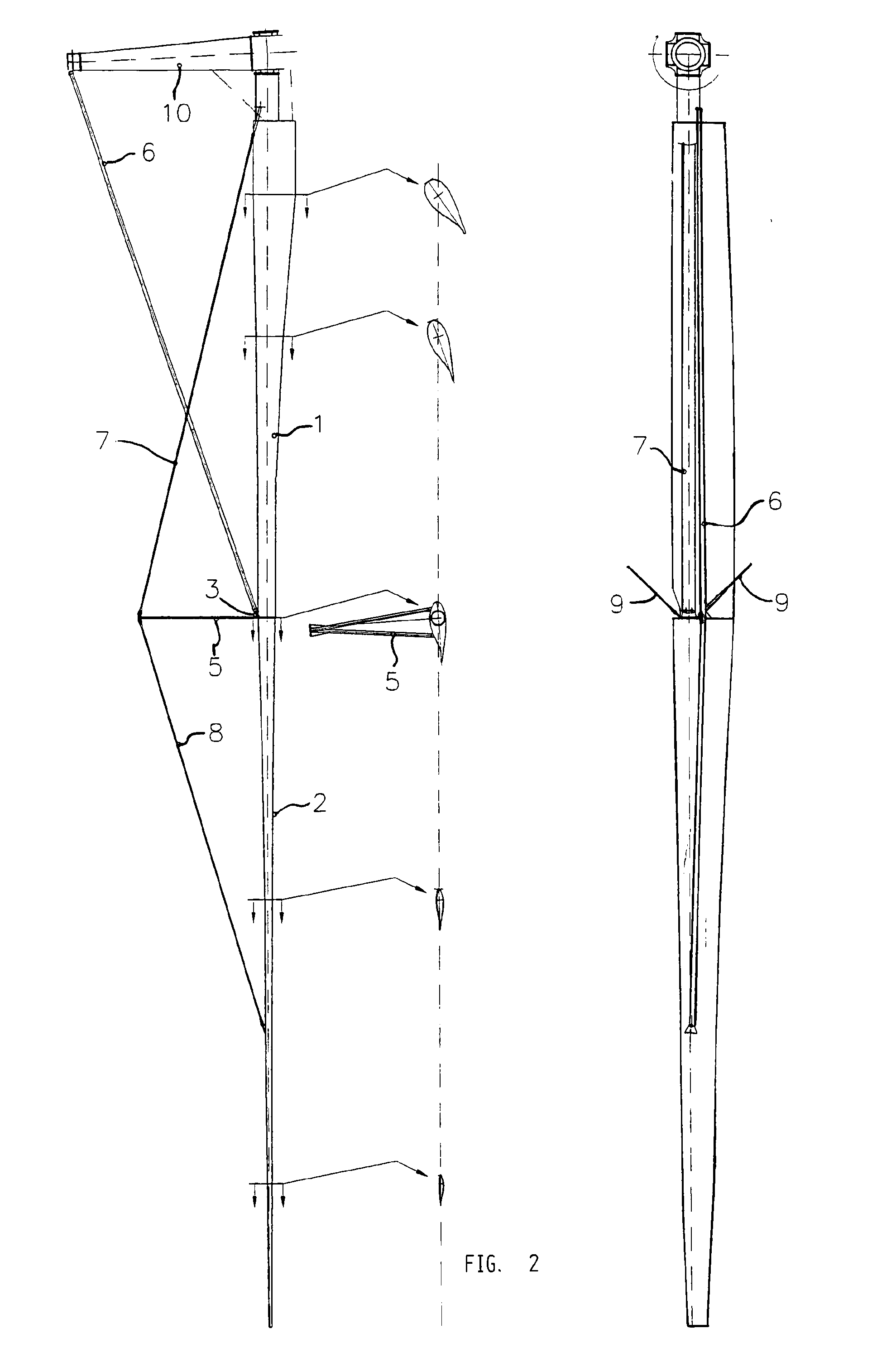
[0044]FIGS. 2 and 3 present a two-piece rotor blade (20, 30) with corresponding joining and stiffening elements. In this embodiment example each rotor blade comprises an inner (1) and an outer rotor blade part (2) divided in two somewhat on the inner side of the middle of the rotor blade. The rotor blade parts (1, 2) are held together by joining elements in the form of a tubular connection (11) which exten...


PUM


Abstract

Wind power plant rotor comprising one or more rotor blades and stiffening elements to stiffen the rotor, where the rotor blades are arranged such that they can turn around their longitudinal axes relative to corresponding rotor stiffening elements. Each rotor blade may comprise at least two rotor blade parts where the outer rotor blade part may be turnably arranged relative to the inner rotor blade part. The solution facilitates use of longer or slimmer rotor blades while strength and stiffness increase. The fatigue forces are thereby reduced while the corresponding tower structure can be made stiffer and lighter. Manufacturing and transport costs are reduced.Further, the stiffening elements may be formed with an aerodynamic outer cross section as for example a drop profile or wing profile in order to reduce air drag and audible noise.

Description

CROSS REFERENCE TO RELATED APPLICATION(S)[0001]This application is a 35 U.S.C. §371 National Phase Entry Application from PCT / NO2008 / 000060, filed Feb. 15, 2008, and designating the United States. This application also claims the benefit of Norwegian Patent Application No. 20071370 filed Mar. 14, 2007, the disclosure of which is incorporated herein in its entirety by reference.AREA OF THE INVENTION[0002]The invention generally relates to wind power based exploitation of energy. More specifically the invention relates to wind power plant rotor. Concretely the invention relates to a stiffened wind power plant rotor where each rotor blade is turnably arranged around its own length axis relative to rotor stiffening elements.PRIOR ART[0003]Energy from wind is currently competing with an increasing number of different types of energy sources. It is crucial that wind turbines are built in a simple and good manner, and that they are efficient in operation. The trend of recent years is to bu...

Claims


Application Information

Patent Timeline
Patent Type & Authority Patents(United States)
IPC IPC(8): F01D5/22
CPCF03D7/0224F03D1/0675F03D11/00Y02E10/722Y02E10/723Y02E10/721F05B2260/96F03D7/02F03D1/06Y02E10/72Y02P70/50
Inventor HOLMOY, VIDAR
Owner HOLMOY VIDAR
Why Eureka
Try Eureka