Power tool

a technology of power tools and power tools, which is applied in the field of power tools, can solve the problems of increasing the manufacturing cost of power tools, the cost of waterproofed electric components, and the inability to meet the requirements so as to improve the dustproof and waterproof properties, prevent the increase of the manufacturing cost of the power tool, and streamline the forming or molding operation.

Active Publication Date: 2011-04-14
MAKITA CORP
View PDF9 Cites 18 Cited by
  • Summary
  • Abstract
  • Description
  • Claims
  • Application Information

AI Technical Summary

Benefits of technology

[0016]According to the configuration described above in the first aspect, an electric component is surrounded by the two receptacle blocks and the seal layer formed integrally with at least one of the two receptacle blocks serves to provide sealing between opposed surfaces of the two receptacle blocks when the two divisional housings are combined together. Therefore, the power tool is securely sealed at the opposed surfaces of the two receptacle blocks and thus rendered excellent in dustproof and waterproof properties for the electric component.
[0017]Furthermore, the waterproof property provided for the electric component by the seal layer as described above may obviate the need to use an expensive waterproofed electric component. As a result, the increase in the manufacturing cost for the power tool can be prevented.
[0018]According to the configuration with the additional feature described above in the second aspect, the seal layer does not have to be fabricated independently of an outer surface layer formed on an outer surface of the divisional housing on which the one or each of the two receptacle blocks is formed integrally with the seal layer, and thus can be formed simultaneously with the outer surface layer. This makes it possible to streamline the forming or molding operation and to reduce the number of parts to be formed.
[0019]According to the configuration with the additional feature described above in the third aspect, the first and second seal layers of an elastic material are deformed and brought into hermetical contact with each other when the two divisional housings are combined together. Therefore, the electric component is surrounded by the two receptacle blocks and provided with an improved capability of sealing between the first and second seal layers, so that the dustproof and waterproof properties for the electric component can be enhanced.

Problems solved by technology

Thus, there is apprehension that the waterproof and dustproof properties for the electric component could possibly be diminished.
Moreover, electric components waterproofed as described above may generally be expensive.
Therefore, it is also apprehended that the use of a waterproofed electric component should entail an increase in the manufacturing cost of the power tool.

Method used


Image

  • Power tool
  • Power tool
  • Power tool

Examples


first embodiment

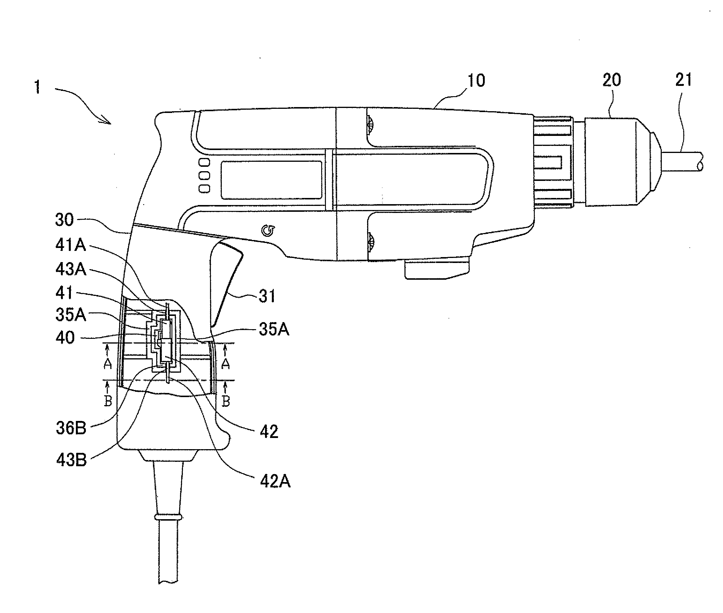
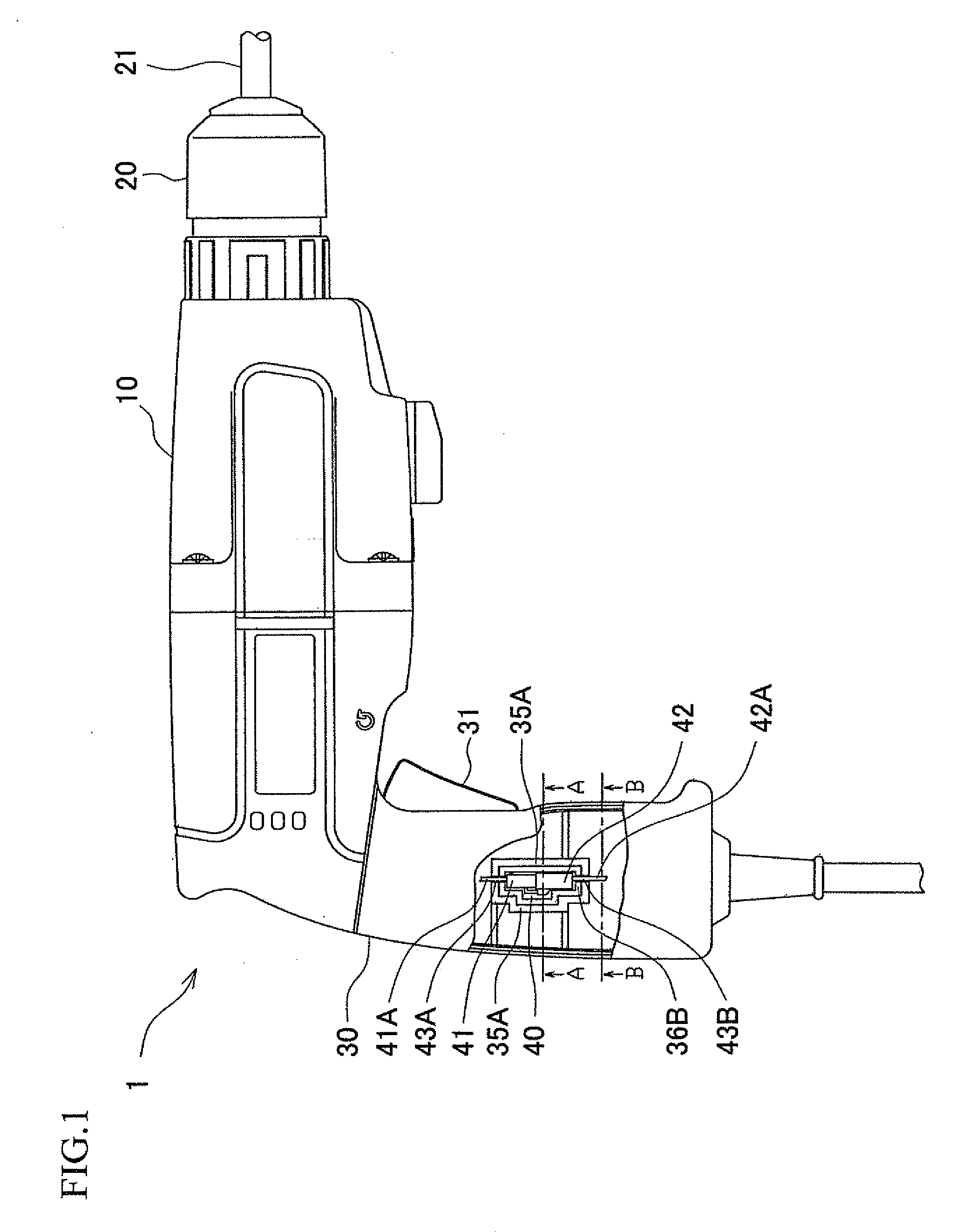
[0028]A first embodiment of the present invention will be described hereinafter with reference to FIGS. 1, 2A and 2B. A hammer drill 1 shown in FIG. 1 includes a main body housing 10, a drill chuck 20, and a handle 30. The hammer drill 1 is one example of a power tool consistent with the present invention.

[0029]The main body housing 10 is made of plastic and shaped in a tubular form. The main body housing 10 accommodates a motor, a rotation transmission mechanism, and other components.

[0030]The drill chuck 20 is provided at a front end of the main body housing 10 and configured to protrude therefrom frontward of the main body housing 10. The drill chuck 20 is mounted on a tool holder (not shown) which protrudes frontward from the main body housing 10. At a front end of the drill chuck 20, a drill bit 21 is detachably installed to the drill chuck 20.

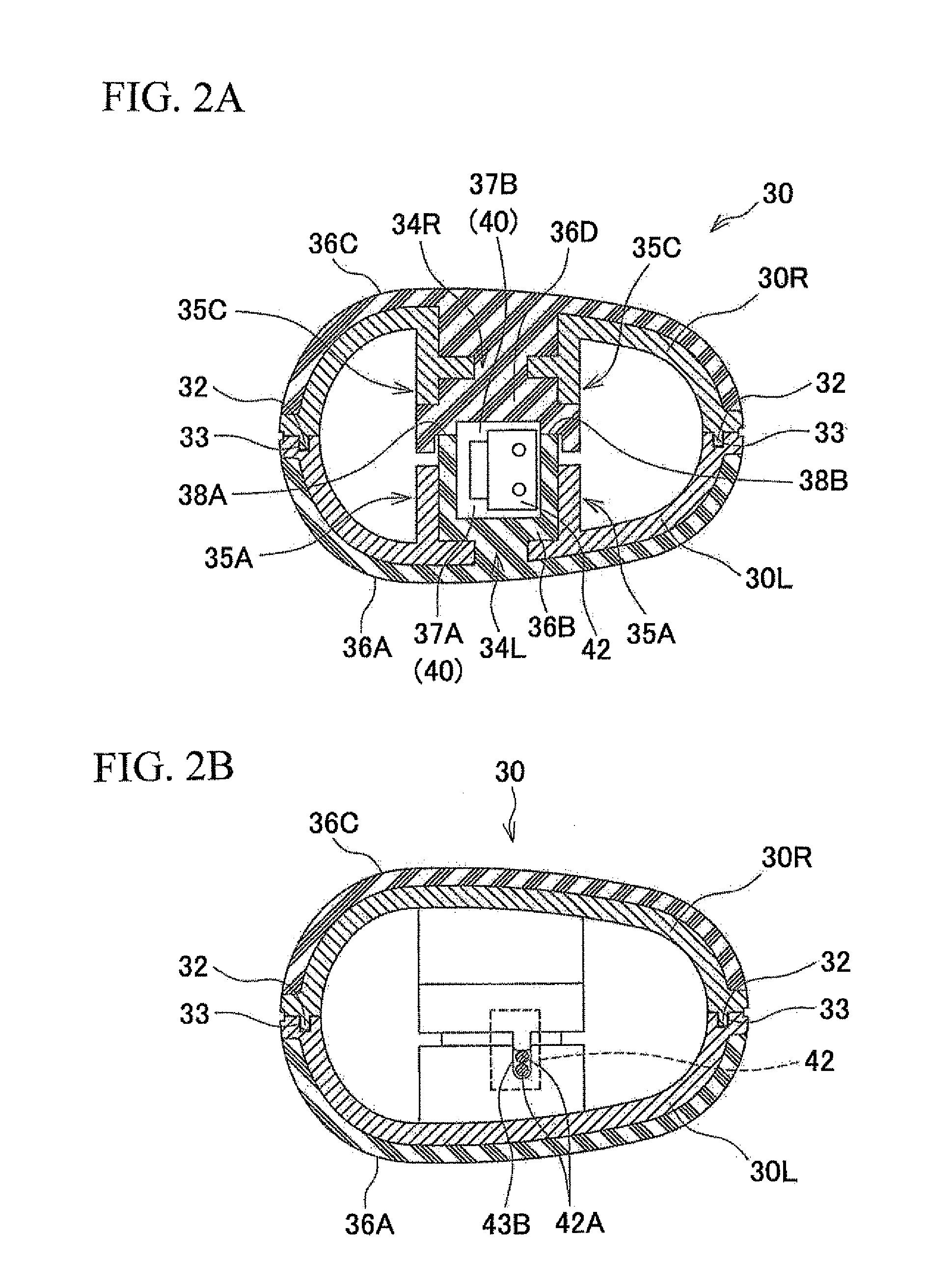
[0031]The handle 30 is configured to be able to be vertically separable into two, left and right halves. As shown in FIGS. 2A and 2B, th...

second embodiment

[0048]A second embodiment of the present invention will be described hereinafter with reference to FIGS. 1, 3A and 3B. The same elements as in the first embodiment are designated by the same reference characters, and a duplicate description thereof will be omitted. As shown in FIGS. 3A and 3B, in the hammer drill 1 according to this embodiment, the second right handle portion 30R described above is replaced by a third right handle portion 50R. The third right handle portion 50R is formed of plastic and is one example of a divisional housing consistent with the present invention.

[0049]As shown in FIGS. 3A and 3B, locator ridges 52 are formed on front and rear end faces, both facing leftward, of the third right handle portion 50R. As will be described later, these front and rear locator ridges 52 are fitted in the front and rear locator channels 33, respectively.

[0050]As shown in FIG. 3A, on an inner surface of the third right handle portion 50R, a receptacle block 55C is provided and...

third embodiment

[0057]A third embodiment of the present invention will be described hereinafter with reference to FIGS. 1, 4A and 4B. The same elements as in the first and second embodiments are designated by the same reference characters, and a duplicate description thereof will be omitted. As shown in FIGS. 4A and 4B, in the hammer drill 1 according to this embodiment, the first left handle portion 30L described above is replaced by a fourth left handle portion 60L. The fourth left handle portion 60L is formed of plastic, and additionally is one example of a divisional housing consistent with the present invention.

[0058]As shown in FIGS. 4A and 4B, locator channels 63 are formed on front and rear end faces, both facing rightward, of the fourth left handle portion 60L. The front and rear locator ridges 52 as in the second embodiment are fitted in these front and rear locator channels 63, respectively.

[0059]As shown in FIG. 4A, on an inner surface of the fourth left handle portion 60L, a receptacle...


PUM

PropertyMeasurementUnit
elasticaaaaaaaaaa
waterproofaaaaaaaaaa
waterproof propertiesaaaaaaaaaa

Abstract

In a power tool, a housing is composed of two divisional housings to be combined together; two receptacle blocks are provided on inner surfaces of the two divisional housings, respectively, and configured to protrude opposite to each other from the inner surfaces of the two divisional housings to surround an electric component and to hold the electric component in place when the two divisional housings are combined together into the housing; and a seal layer of an elastic material is formed integrally with one or each of the two receptacle blocks. The seal layer formed on a first receptacle block is pressed against a second receptacle block or another seal layer formed on the second receptacle block to provide sealing between opposed surfaces of the two receptacle blocks when the two divisional housings are combined together.

Description

BACKGROUND OF THE INVENTION[0001]This application claims the entire benefit of Japanese Patent Application Number 2009-237523 filed on Oct. 14, 2009, the entirety of which is incorporated by reference.TECHNICAL FIELD[0002]This invention relates to a power tool comprising a housing composed of two divisional housings to be combined together, and receptacle blocks provided on inner surfaces of the two divisional housings respectively and configured to protrude therefrom opposite to each other so as to surround an electric component, and to hold the electric component in place when the two divisional housings are combined together into the housing.BACKGROUND ART[0003]In a power tool of various kinds, typically, when an electric component is to be housed in its housing composed of two divisional housings, a seal material made of rubber or the like is adhered to the abutting end faces of the two divisional housings to remove an interstice therebetween, in order to provide waterproof and ...

Claims


Application Information

Patent Timeline
Patent Type & Authority Applications(United States)
IPC IPC(8): B25F5/02
CPCB25F5/02
Inventor NISHIKIMI, JUNICHIKAKIUCHI, YASUHIRO
Owner MAKITA CORP
Why Eureka
Try Eureka