
Increased efficiency strainer system

a strainer and efficiency technology, applied in the direction of separation process, nuclear element, filtration separation, etc., can solve the problems of affecting the efficiency of the strainer, affecting the efficiency of the emergency core cooling system, and affecting the cooling effect, so as to reduce the required strainer surface area, reduce the maximum differential pressure experienced, and reduce the head loss

Active Publication Date: 2011-04-14
CONTROL COMPONENTS INC
View PDF16 Cites 1 Cited by
  • Summary
  • Abstract
  • Description
  • Claims
  • Application Information

AI Technical Summary

Benefits of technology

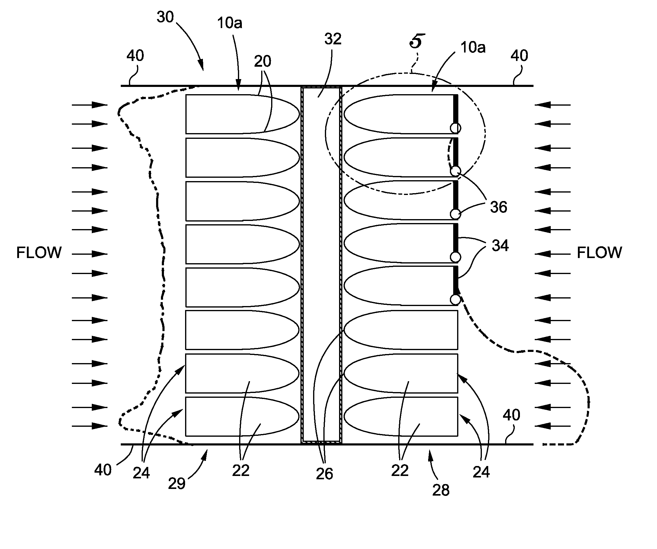
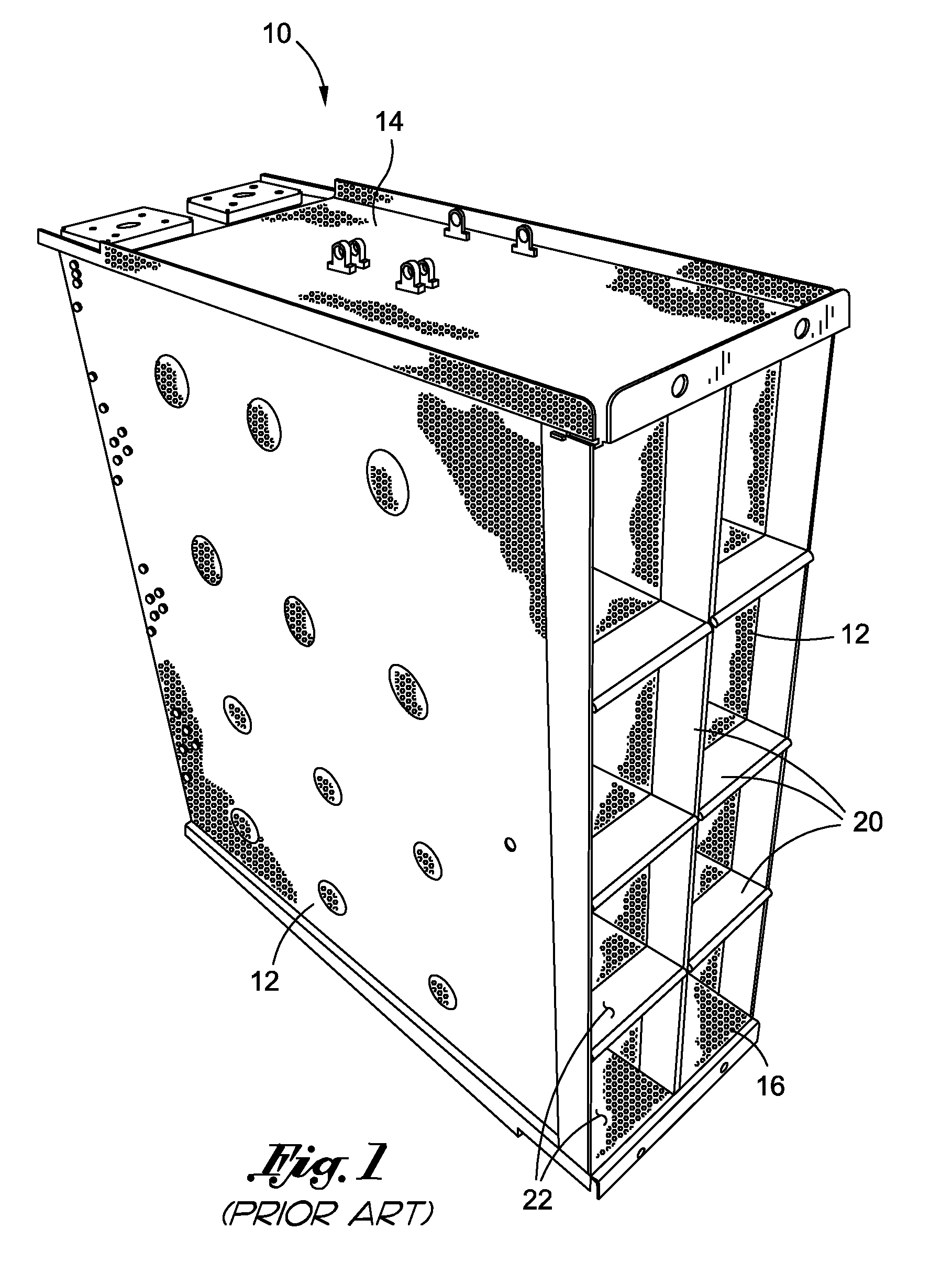
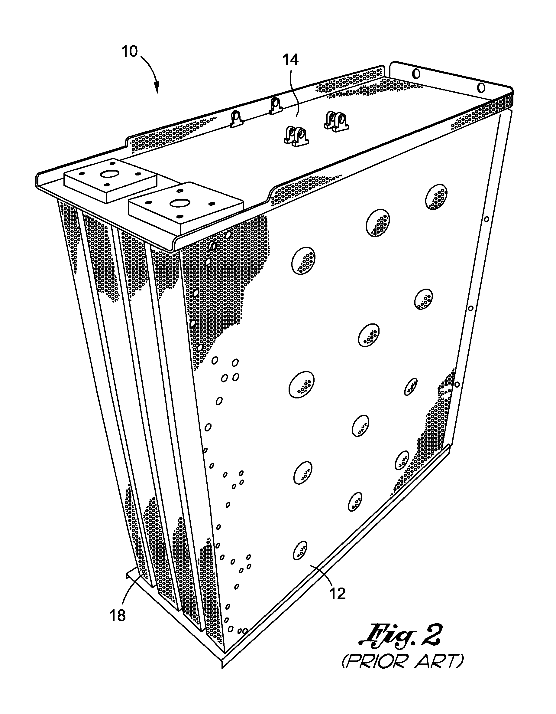
[0013]More particularly, in one embodiment of the present invention, each cartridge has a generally quadrangular configuration, as do the individual strainer pockets included therein. In this particular embodiment, the strainer pockets of the cartridge each define an inflow end, with the inflow ends of the strainer pockets of the cartridge facing in a common direction. Within the cartridge, or the module including multiple cartridges, the inflow ends of one or more of the strainer pockets may be enclosed by an elastic metal membrane. When in a closed position, the membrane prevents liquid flow into the corresponding strainer pocket via the inflow end thereof. The membrane remains closed when only a low pressure load is exerted thereon, but is deflected or deformed into an open position when a high pressure load is exerted thereon. The movement of the membrane to its open position effectively opens the corresponding strainer pocket, thus allowing for the flow of liquid into the interior of the strainer pocket via the inflow end thereof.
[0014]In accordance with another aspect of the present invention, it is contemplated that the above-described strainer cartridge(s) included in a strainer module of the strainer system may include flat, non-perforated face plates which extend from a surface of the cartridge(s) adjacent the inflow ends of the strainer pockets thereof. The non-perforated extended face plates cause the edges of a fiber and particulate debris bed forming at the inflow ends of the strainer pockets to compress and slowly curl in from an originally flush relationship to the face plates, which results in the creation of small flow paths between the face plates and debris bed as differential pressure continues to rise, thus allowing flow into the strainer and reducing head loss. As the strainer area affected by the flow receives more debris, fiber, particulate and chemical precipitate, the head loss increases until another flow path is opened into another area of the strainer. The creation of the flow paths, as caused by the optional inclusion of the extended face plates with the strainer cartridge(s), effectively reduces the maximum differential pressure experienced across the strainer and provides a way to potentially reduce required strainer surface area necessary to satisfy a particular containment recirculation net positive suction head requirement.
[0019]In the embodiment of the strainer system including the pressure released membrane in the plenum duct, the activation of the originally isolated strainer module is facilitated by the movement of the pressure released membrane from an original closed position, to an open position. When the pressure released membrane is in its closed position, it effectively blocks that portion of the plenum duct fluidly communicating with the isolated strainer module from the remainder of the plenum duct which is fluidly coupled to the originally active strainer modules and the suction pump. As indicated above, an increase in the suction pressure level within that portion of the plenum duct fluidly communicating with the originally active strainer modules beyond a prescribed threshold facilitates the movement of the pressure released membrane from its closed position to its open position, thus placing that portion of the plenum duct in fluid communication with the originally inactive strainer module into fluid communication with the remainder of the plenum duct. Such fluid communication in turn allows the operating suction pump to effectively draw fluid through the previously isolated and now active strainer module of the strainer system.

Problems solved by technology

A loss of coolant accident can involve the failure of reactor components that introduce large quantities of solid matter into the cooling water, which entrains the solids and carries them back to the suppression pool.
Thus, in both types of reactors (i.e., boiling water reactors and pressurized water reactors), cooling water is drawn from a reservoir and pumped to the reactor core, with entrained solids or debris potentially impairing cooling and damaging the emergency core cooling system pumps if permitted to circulate with the water.
There has been considerable effort expended in the prior art in relation to the design of strainers to decrease head loss across the strainer for the desired coolant flow.
The resulting fibrous debris bed on the strainer surfaces can quickly block the flow through the strainer, even though the trapped particulates may be small enough to pass through the strainer perforations.
This solution, however, is often undesirable since the available space in a reactor for a suction strainer is usually limited, and further because larger strainers are typically more costly.
As a result, the situation sometimes arises wherein the expected debris load after a loss of coolant accident can dictate a need for strainers that are too large for the space allotted for them in the containment area.
Moreover, large strainers are often more difficult work with and thus more costly to install.
In addition, prior art emergency core cooling system strainers have been constructed in ways that make them somewhat expensive to fabricate.

Method used


Image

  • Increased efficiency strainer system
  • Increased efficiency strainer system
  • Increased efficiency strainer system

Examples


second embodiment

[0050]Referring now to FIGS. 6-8, there is shown a strainer module 100 constructed in accordance with the present invention. The strainer module 100 comprises a generally cylindrical, tubular main body section 102 which defines a section plenum 104 extending axially therethrough. Extending radially from the outer surface of the main body section 102 in spaced, generally parallel relation to each other are a plurality of circularly configured separator plates 106. Though not shown in FIG. 6, the main body section 102 includes openings formed therein which allow liquid flowing between the separator plates 106 to be drawn into the suction plenum 104 via such openings upon the creation of a pressure differential condition attributable to the activation of a pump fluidly coupled to the suction plenum 104.

[0051]The strainer module 100 further comprises at least one circularly configured strainer cartridge 108 which is positioned between a prescribed adjacent pair of the separator plates 1...

third embodiment

[0055]Referring now to FIG. 9, there is shown a strainer module 200 constructed in accordance with the present invention. The sole distinction between the strainer modules 100, 200 lies in the separator plates 206 included in the strainer module 200 each having a generally quadrangular (e.g. square) configuration, as opposed to the circular configuration of the above-described separator plates 106 included in the strainer module 100.

fourth embodiment

[0056]Referring now to FIGS. 10 and 11, there is shown a strainer module 400 constructed in accordance with the present invention. The strainer module 400 comprises a main body section 402 which has a generally quadrangular cross-sectional configuration and defines a suction plenum 404. Attached to a common wall of the main body section 402 and protruding therefrom in spaced, generally parallel relation to each other are a plurality of (e.g., four) cylindrically configured, tubular primary strainer elements 406 which each fluidly communicate with the suction plenum 404. Each of the primary strainer elements 406 defines an inflow end 408, and comprises concentrically positioned outer and inner walls 410, 412. The outer and inner walls 410, 412 are each fabricated from a perforated metal, mesh-like material. The inflow end 408 is typically defined solely by the inner wall 412 of the primary strainer element 406.

[0057]In the exemplary strainer module 400, the inflow end 408 of one of t...


PUM

PropertyMeasurementUnit
elasticaaaaaaaaaa
pressureaaaaaaaaaa
head lossaaaaaaaaaa

Abstract

In accordance with the present invention, there is provided a strainer system comprising a plurality of strainer modules, each of which comprises multiple cassettes or cartridges assembled together in a prescribed arrangement. In the strainer system constructed in accordance with the present invention, the “clean” sides of the strainer modules are fluidly connected to each other by a plenum duct which also has a suction pump fluidly coupled thereto. Integrated into the plenum duct is a pressure released membrane (PRM) which is positioned so as to effectively isolate one of the strainer modules from the remaining active strainer modules included in the strainer system. The pressure released membrane is uniquely configured so as to facilitate the activation of the isolated strainer module when pressure across the plenum duct increases beyond a prescribed threshold.

Description

CROSS-REFERENCE TO RELATED APPLICATIONS[0001]The present application is a continuation-in-part of U.S. patent application Ser. No. 12 / 578,413 entitled INCREASED EFFICIENCY STRAINER SYSTEM filed Oct. 13, 2009, the disclosure of which is incorporated herein by reference.STATEMENT RE: FEDERALLY SPONSORED RESEARCH / DEVELOPMENT[0002]Not ApplicableBACKGROUND OF THE INVENTION[0003]1. Technical Field of the Invention[0004]The present invention relates generally to strainer devices and, more particularly, to a strainer system wherein a pressure released membrane is integrated into the plenum duct at the “clean” side of multiple strainer modules. The pressure released membrane is operative to isolate one of the strainer modules of the strainer system from the remaining active strainer modules thereof, and to effectively activate the isolated strainer module when pressure across the plenum duct increases beyond a prescribed threshold as a result of a head loss increase across the originally act...

Claims


Application Information

Patent Timeline
Patent Type & Authority Applications(United States)
IPC IPC(8): B01D29/60B01D29/56
CPCB01D35/147B01D35/1475G21C19/307B01D35/1576B01D35/1573
Inventor KIELBOWICZ, STANISLAWPRATHER, CARL W.
Owner CONTROL COMPONENTS INC
Learn More