3-phase faraday optical current sensor assembly

a technology of optical current and sensor assembly, which is applied in the direction of electrical testing, measurement devices, instruments, etc., can solve the problems of not being able to separate phases, cumbersome and also a security risk, and the overhead line is more exposed to environmental influences, so as to achieve less compactness, more security and stability, and more stability

Active Publication Date: 2011-04-14
LANDIS & GYR OY
View PDF14 Cites 13 Cited by
  • Summary
  • Abstract
  • Description
  • Claims
  • Application Information

AI Technical Summary

Benefits of technology

[0042]For more stability two circular plates may be used. The above structure is similar to the previous structure, however slightly less compact but offers more security and stability provided by the second circular plate. It also offers a better protection of the optical conduits since they may be attached to the bars. Alternatively, a plate may be used instead of or in addition to the bars.
[0043]According to a further feature of the method according to the present invention the Faraday optical current sensors may be fixated at substantially equal distance from the 3-phase cable in relation to the radial dimension and/or the longitudinal dimension. To allow a simple positioning and accurate calibration each Faraday optical current sensor should be placed at the same distance from its corresponding phase conductor. Additionally, the longitudinal position of the Faraday optical current sensors should be equal, since the

Problems solved by technology

However, overhead lines have the drawback of being more exposed to environmental influences such as storms, blizzards and the like.
This is very cumbersome and also a security risk, since the outer insulation and the shield must be removed from the cable.
For very high voltages it is not always possible to separate the phases, or the measurement equipment needed would occupy a very large space due to the large insulation distances needed.
Possible sources of errors include sensor position in relation to the power line, optical noise, magnetic noise, transiti

Method used


Image

  • 3-phase faraday optical current sensor assembly
  • 3-phase faraday optical current sensor assembly
  • 3-phase faraday optical current sensor assembly

Examples


numerical example

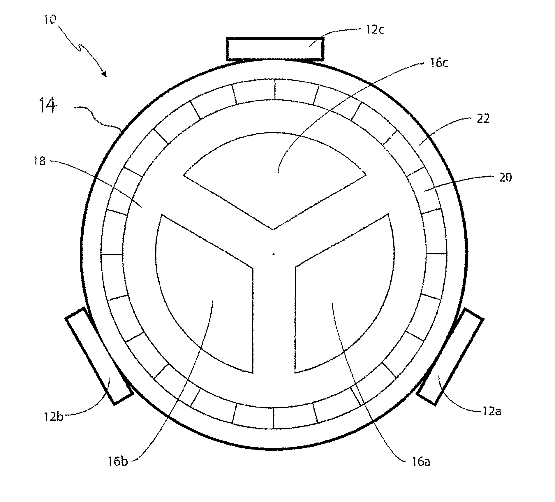
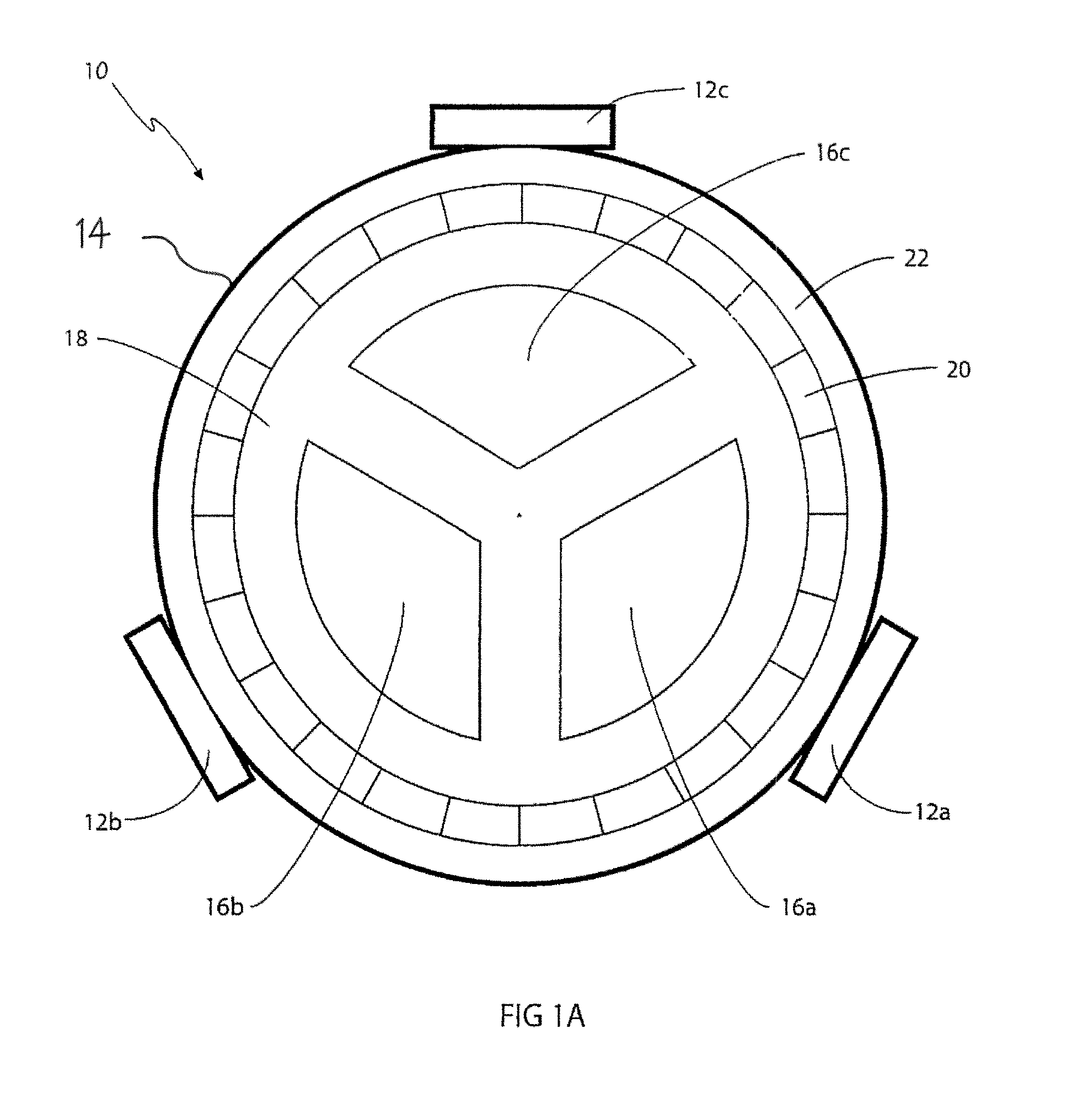
[0074]The teachings according to the present invention have been applied to calculate the current in the 12 kV 3-phase cable 14 of FIG. 1. The 12 kV 3-phase cable 14 has the following numerical properties:

[0075]Thickness of the high voltage insulation: 5 mm

[0076]Shield 20 thickness: 1 mm

[0077]Outer insulation 22 thickness: 3.5 mm

[0078]Overall diameter: 57 mm

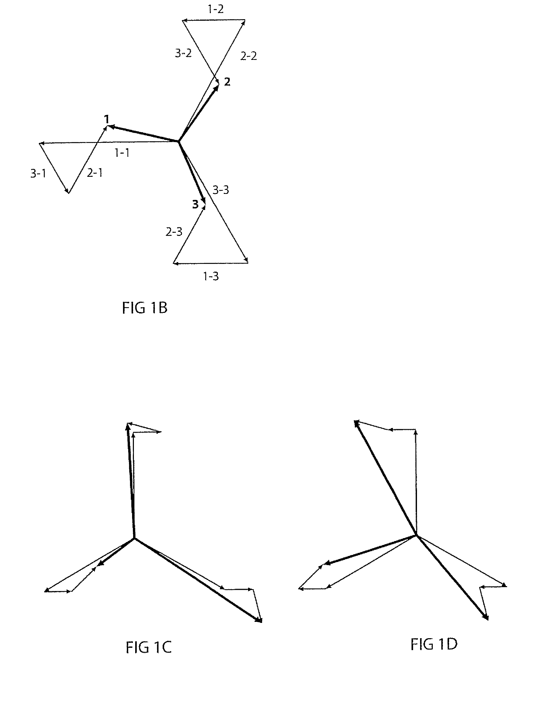
[0079]From the above numerical properties, the relative theoretical contribution to the magnetic field from the 3-phase currents and the shield at the position of the sensor element along the direction of the sensor element may be determined. The relative theoretical contribution to the magnetic field measured by the Faraday optical current sensor 12a positioned juxtaposed the conductor 16a of phase 1 has been listed below.

[0080]Phase 1: 100%

[0081]Phase 2: 55%

[0082]Phase 3: 55%

[0083]Shield: 70%

[0084]The contribution to the magnetic field from phase 1 has been designated 100%. Each contribution is considered a vector component. Th...


PUM


Abstract

The object of the invention is to provide a method and a system for fixating a Faraday optical current sensor (12a, 12b, 12c) in a suitable measurement position for measuring the current in a 3-phase cable (14). The 3-phase cable (14) comprises 3 individual section-shaped phase conductors (16a, 16b, 16c) insulated in relation to one another and encapsulated inside an insulator (18). The method comprises the provision of a Faraday optical current sensor arrangement comprising 3 Faraday optical current sensors (12a, 12b, 12c), each Faraday optical current sensor being fixated in a specific position outside the section-shaped phase conductors (16a, 16b, 16c), and the provision of a processing unit for calculating a current value from a magnetic field value. The method is performed by measuring 3 magnetic field values by using each of the 3 Faraday optical current sensors (12a, 12b, 12c) and calculating the current in each of the section-shaped phase conductors (16a, 16b, 16c) by using the processing unit and the 3 magnetic field values.

Description

CROSS-REFERENCE TO RELATED APPLICATION[0001]This application is a national phase filing, under 35 U.S.C. §371(c), of International Application No. PCT / EP2009 / 059364, filed Jul. 21, 2009, the disclosure of which is incorporated herein by reference in its entirety.FEDERALLY SPONSORED RESEARCH OR DEVELOPMENT[0002]Not ApplicableBACKGROUND OF THE INVENTION[0003]3-phase medium voltage cables are used in numerous applications for distributing electrical energy from generators or substations to consumers. 3-phase cables are typically used as a distribution network to feed electrical motors or power electronic equipment. In such a 3-phase cable network there is a need to measure the current being distributed to the consumer. The current must be measured to determine and log the power being transmitted to each consumer and to be able to react in case of malfunctions or failures such as a short-circuit occurring in the distribution network. Historically, cable networks were used for low voltag...

Claims


Application Information

Patent Timeline
IPC IPC(8): G01R31/00
CPCG01R15/247G01R15/246
Inventor SORENSEN, FREDDY
Owner LANDIS & GYR OY
Why Eureka
Try Eureka