Optical element, device, method, and applications

a technology of optical elements and apertures, applied in the field of coded aperture optics, can solve the problems that conventional refractive and reflective optical components (e.g., lenses, mirrors) are not useful for imaging non-focusable radiation

Inactive Publication Date: 2011-04-14
UNIVERSITY OF ROCHESTER
View PDF11 Cites 61 Cited by
  • Summary
  • Abstract
  • Description
  • Claims
  • Application Information

AI Technical Summary

Problems solved by technology

Conventional refractive and reflective optical components (e.g., lenses, mirrors) are not useful for imaging nonfocusable radiation such as, e.g., γ-rays and X-rays.
However, a simple pinhole camera can be used as an imaging device for γ-rays and X-rays because diffraction effects are minimal, in contrast to those effects in the UV to sub-millimeter and, particularly the visible, regime, which cannot be ignored.

Method used


Image

  • Optical element, device, method, and applications
  • Optical element, device, method, and applications
  • Optical element, device, method, and applications

Examples


Embodiment Construction

[0025]Reference will now be made in detail to the present exemplary embodiments of the invention, non-limiting examples of which are illustrated in the accompanying drawings. Wherever possible, the same reference numbers will be used throughout the drawings to refer to the same or like parts.

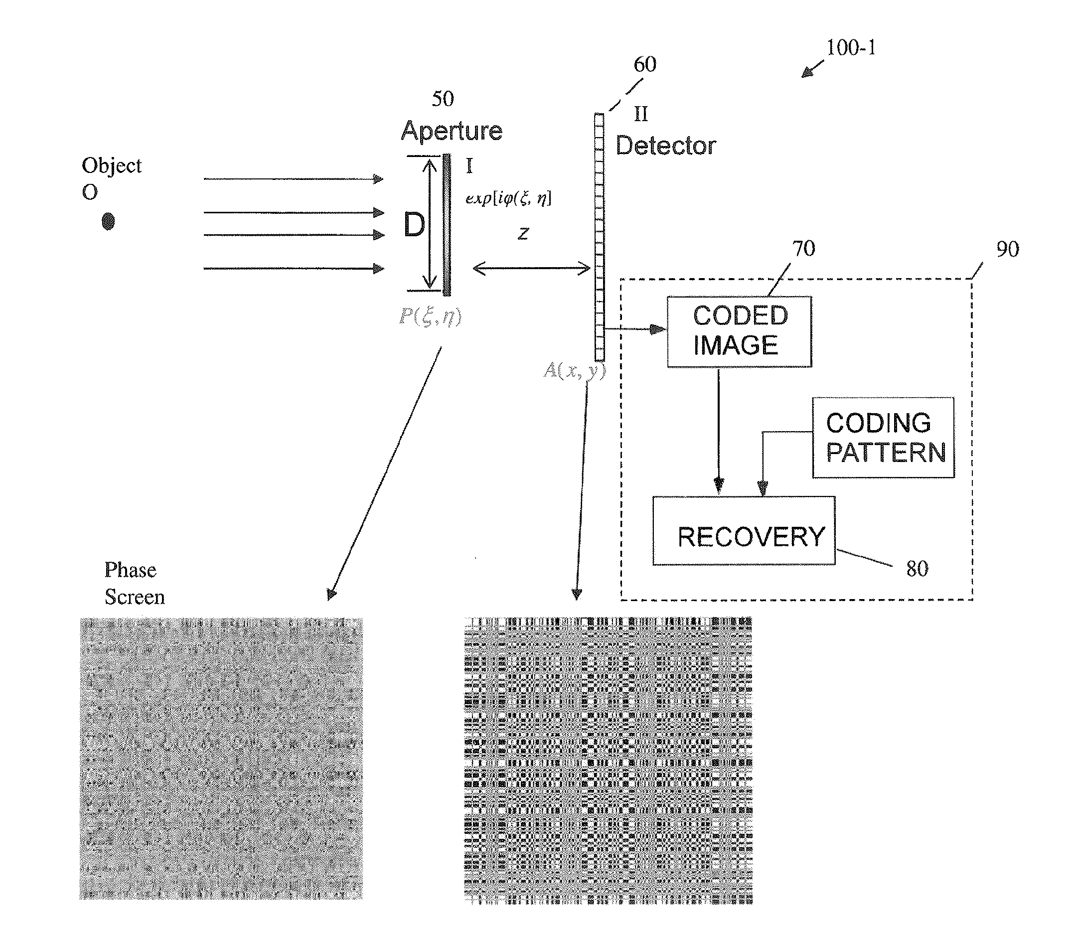
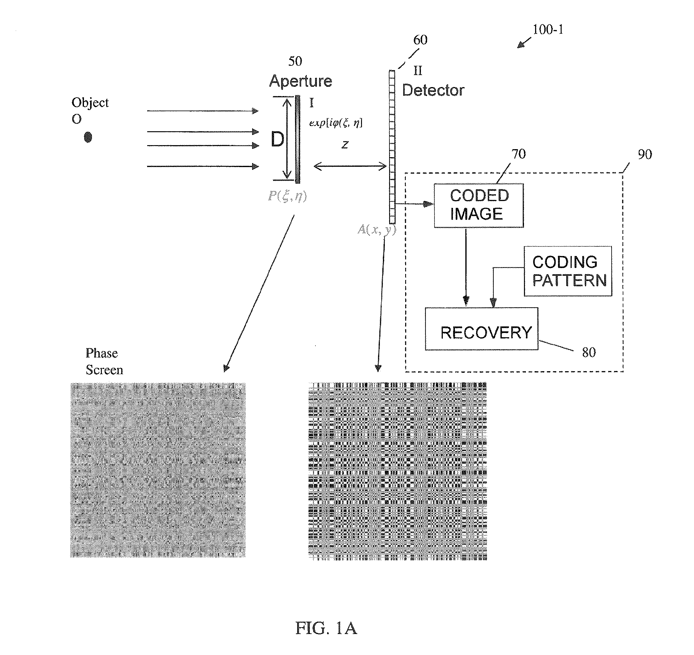
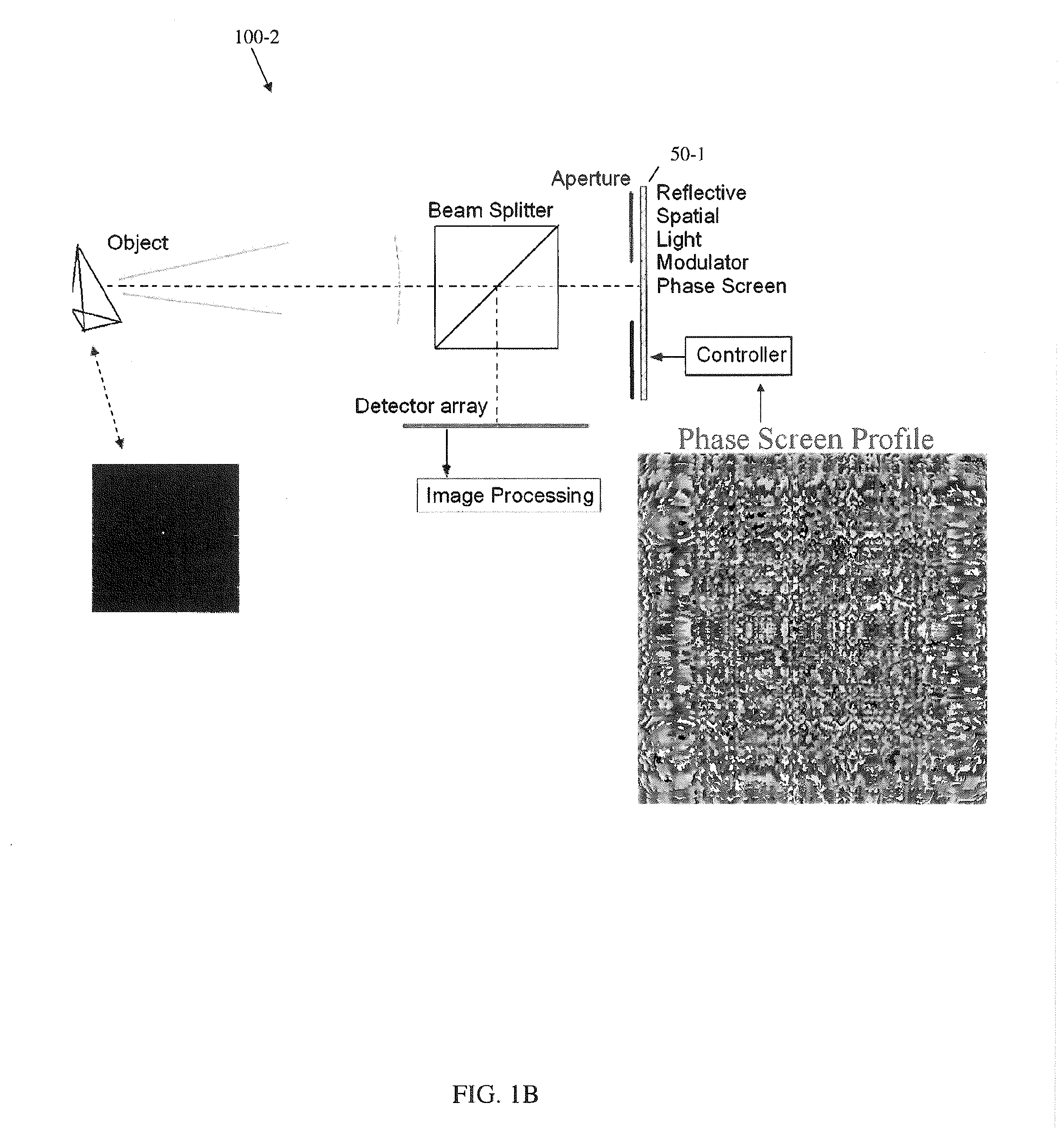
[0026]As used herein, the term “focusable” radiation or light when used in conjunction with the embodied optical element for generating a band-limited uniformly redundant array (bl-URA), means electromagnetic radiation spanning the UV through IR spectrum, which can be focused by a refractive or a reflective optical component, unlike gamma (γ)- or X-rays, which are referred to in the art as nonfocusable radiation. The term “focusable” radiation or light, when used in conjunction with the embodied optical imaging device, additionally refers to wavelengths for which diffraction effects are no longer negligible, as understood in the art.

[0027]The exemplary optical element and imaging device embodime...


PUM

PropertyMeasurementUnit
light transmission functionaaaaaaaaaa
amplitude/phaseaaaaaaaaaa
surface dimensionsaaaaaaaaaa

Abstract

A novel phase-coded aperture, associated imaging system, and design method is disclosed. The optical imaging system includes a coded-aperture followed optically by a detector array and includes an image processor. A diffraction pattern in the form of a band-limited uniformly redundant array is formed on the detector array when focusable radiation from a point source in object space is modulation by the transmission function of the coded-aperture. Since diffraction effects cannot be ignored in the optical regime, an iterative phase retrieval method is used to calculate the phase-coded aperture transmission function. Correlation type processing can be applied for the image recovery.

Description

CROSS-REFERENCE TO RELATED APPLICATIONS[0001]This application claims priority to U.S. provisional Patent Application Ser. No. 61 / 250,224 filed on Oct. 9, 2009, the content of which is incorporated herein by reference in its entirety.FEDERALLY SPONSORED RESEARCH[0002]This invention was made with government support from the U.S. Army Research Office under contract number W911NF-09-1-0425. The government has rights in this invention.BACKGROUND OF THE INVENTION[0003]1. Field of the Invention[0004]Embodiments of the present invention relate generally to coded aperture optics, systems, and methods operable with and pertaining to focusable radiation and, more particularly, to an optical element for generating a band-limited uniformly redundant array (bl-URA) from light within a spectrum of focusable radiation, an optical imaging device incorporating the optical element, and a method for determining a transmission function P(ξ, η) for an optical element that will generate a desired intensit...

Claims


Application Information

Patent Timeline
Patent Type & Authority Applications(United States)
IPC IPC(8): H04N5/228G02F1/35
CPCG02F2203/01G02F2203/02G02F2203/12G02F2203/50H04N5/2254G03H2001/0447G03H2223/13G03H2223/23G03H1/041G02F2203/69G02F1/35
Inventor CHI, WANLIGEORGE, NICHOLAS
Owner UNIVERSITY OF ROCHESTER
Why Eureka
Try Eureka