Focus adjusting apparatus and focus adjusting method

a technology of focus adjustment and focus, which is applied in the direction of camera focusing arrangement, printers, instruments, etc., can solve the problem of reducing the accuracy of focus calculation

Inactive Publication Date: 2011-04-14
CANON KK
View PDF12 Cites 42 Cited by
  • Summary
  • Abstract
  • Description
  • Claims
  • Application Information

AI Technical Summary

Benefits of technology

[0005]An object of the present invention is to achieve high-accuracy focus adjustment even when vignetting is caused by a taking lens.

Problems solved by technology

Therefore, in an area near the in-focus position, where a filter length is small, a correct filter shape cannot be obtained because of, for example, aliasing distortion, and accordingly the focus calculation accuracy is reduced.

Method used


Image

  • Focus adjusting apparatus and focus adjusting method
  • Focus adjusting apparatus and focus adjusting method
  • Focus adjusting apparatus and focus adjusting method

Examples


first embodiment

[0025]A first embodiment of the present invention will be described with reference FIGS. 1 to 14C.

(Structure of Image Pickup Device)

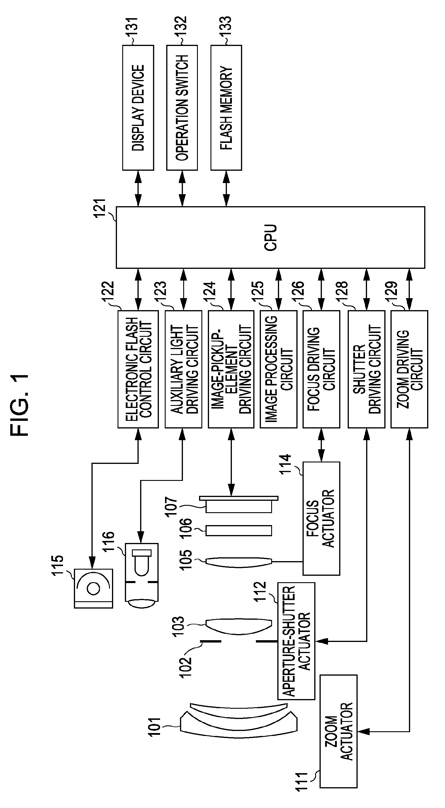
[0026]FIG. 1 is a block diagram of an image pickup device according to the present embodiment. In FIG. 1, reference numeral 101 denotes a first lens unit that is arranged at an end of a taking lens (imaging optical system) and that is held so as to be movable back and forth in an optical axis direction. Reference numeral 102 denotes an aperture-shutter that adjusts an amount of light in a shooting operation by adjusting the aperture diameter of the aperture-shutter and that also functions as a shutter for adjusting an exposure time in an operation of capturing a still image. Reference numeral 103 denotes a second lens unit included in the taking lens. The aperture-shutter 102 and the second lens unit 103 move together back and forth in the optical axis direction to provide a magnification-varying function (zooming function) in cooperation with the back-...

second embodiment

[0086]A second embodiment is a modification of the first embodiment.

(Image Correction Filters Corresponding to F-number)

[0087]In the first embodiment, the pitch of the image correction filters is changed in accordance with the amount of defocus. In contrast, the second embodiment is characterized in that the pitch of the image correction filters is also changed in accordance with the F-number of the taking lens. The operation of the flowchart in FIG. 16 is performed by the CPU 121. The focus adjustment process and the shooting process performed in the optical apparatus according to the second embodiment are similar to those in the optical apparatus according to the first embodiment. Therefore, explanations thereof will be omitted.

[0088]FIGS. 15A, 15B, and 16 are diagrams illustrating the present embodiment, that is, the second embodiment. FIGS. 15A and 15B illustrate the manner in which each image correction filter is formed from the corresponding line spread function in accordance ...


PUM


Abstract

High-accuracy focus adjustment is achieved even when vignetting is caused by a taking lens. A first pixel group receives a light beam that passes through a first pupil area of an optical system that forms an object image, and a second pixel group receives a light beam that passes through a second pupil area. A first signal based on an output signal from the first pixel group and a second signal based on an output signal from the second pixel group are corrected using correction information with a sampling pitch that is changed in accordance with an amount of defocus. A focal state of the optical system is adjusted based on an amount of relative displacement between the corrected first signal and the corrected second signal after the image-signal correction process.

Description

TECHNICAL FIELD[0001]The present invention relates to a focus adjusting apparatus and a focus adjusting method, and more particularly, to an auto-focusing system for use in, for example, an electronic camera.BACKGROUND ART[0002]Japanese Patent Laid-Open No. 4-267211 discloses a solid-state image pickup device which functions as an image pickup element and in which pixels are two-dimensionally arranged. The pixels include microlenses and photoelectric conversion units that are relatively displaced from each other. In the solid-state image pickup device according to Japanese Patent Laid-Open No. 4-267211, in a normal image-capturing operation, an image is formed by adding signals from pixels for which directions of relative displacements between the microlenses and the photoelectric conversion units are different from each other. In an operation of calculating a focus position of a taking lens, the focus position of the taking lens is calculated on the basis of a pair of images obtain...

Claims


Application Information

Patent Timeline
Patent Type & Authority Applications(United States)
IPC IPC(8): G03B13/00H04N5/232
CPCG03B13/36G02B7/34
Inventor TAMAKI, YOSHIHITO
Owner CANON KK
Why Eureka
Try Eureka