
Exhaust gas diffuser

a technology diffuser, which is applied in the field of turbines, can solve the problems of one source of loss and turbulence generation of exhaust gas diffuser, and the loss incurred in this region can have significant impact on the performance and acoustic behavior of the total diffuser system

Inactive Publication Date: 2011-04-21
GENERAL ELECTRIC CO
View PDF45 Cites 84 Cited by
  • Summary
  • Abstract
  • Description
  • Claims
  • Application Information

AI Technical Summary

Benefits of technology

[0010]FIG. 1 is cut-away side

Problems solved by technology

Of course, diffusers are not perfectly efficient.
One source of loss and turbulence generation in exhaust gas diffusers is the result of flow interaction with struts and manways.
Therefore, any loss incurred in this region can have significant impact on the performance and acoustics behavior of the total diffuser system.

Method used


Image

  • Exhaust gas diffuser
  • Exhaust gas diffuser
  • Exhaust gas diffuser

Examples


Embodiment Construction

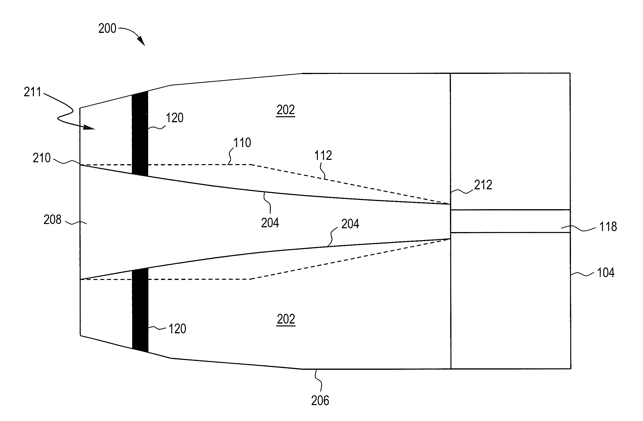
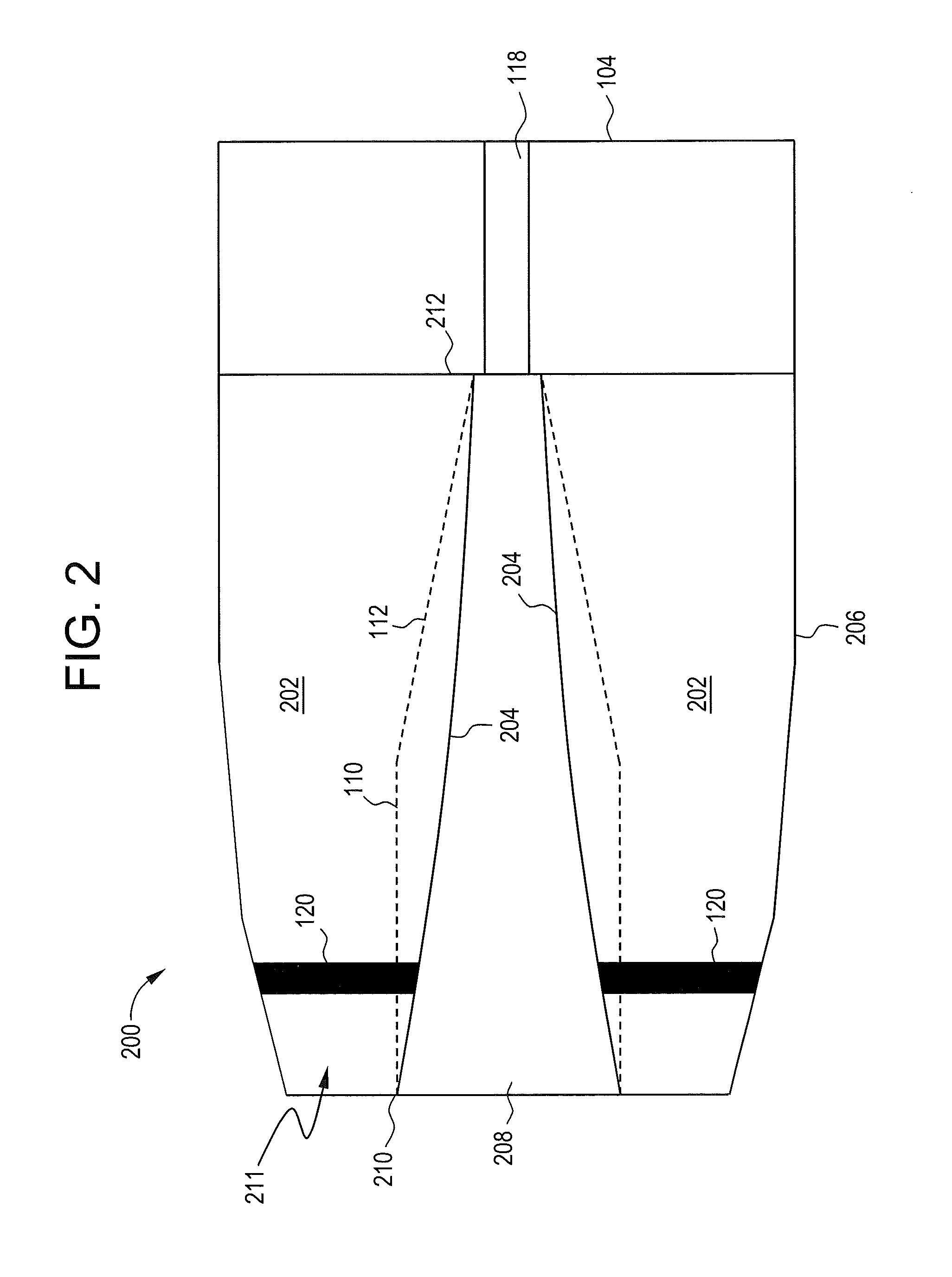
[0020]In one embodiment of the present invention, flow-path area is controlled in the strut passage through shaping of the diffuser inner barrel (inner wall). This flow path shaping is achieved through having maximum opening at the minimum area section in diffuser that is at maximum strut thickness with controlled variation upstream and downstream of strut generates inner wall flow path shape and is often constrained by flow separation from walls. The center body end is the function of center body radius and the diffuser inner wall angle, Similarly casing is shaped retaining the end radius of outer wall and is function of radial swirl. In particular, and contrary to the prior art in which the inner wall includes one or more “flat” sections, the inner wall may, in one embodiment, may be formed such that the inner wall is a curved from the inlet to an end of a center body section of the diffuser. The result is reduced strut blockage and, therefore, a reduction of loss through the stru...


PUM


Abstract

An exhaust gas diffuser includes a center body having an inlet adapted for coupling to a gas turbine, an outer wall, an inner wall and an end downstream from the inlet. The inner wall forms a continuous curve from an entry location to the end. The diffuser also includes a second portion coupled to the end of the of center body.

Description

BACKGROUND OF THE INVENTION[0001]The subject matter disclosed herein relates to turbines and, in particular, to diffusers for use with gas turbines and steam turbines.[0002]Typical gas turbines include a diffuser cone, or diffuser, coupled to the last stage bucket of the rotor. The diffuser serves, generally, to increase static pressure of the exhaust gas by decreasing the kinetic energy of the exhaust gas. Generally, this may be achieved by increasing the cross-sectional area of the diffuser in the direction of exhaust gas flow.[0003]Of course, diffusers are not perfectly efficient. One source of loss and turbulence generation in exhaust gas diffusers is the result of flow interaction with struts and manways. The struts are structural member which transfer the rotor load from a center to an outer casing (outer wall) and then the outer casing transfers the load to a foundation. Aerodynamically, struts present blockages between diffuser inner and outer wall of the diffuser. The inner...

Claims


Application Information

Patent Timeline
IPC IPC(8): F01N1/00
CPCF05D2250/71F01D25/30
Inventor NANDA, DEEPESH DINESH
Owner GENERAL ELECTRIC CO
Features
  • Generate Ideas
  • Intellectual Property
  • Life Sciences
  • Materials
  • Tech Scout
  • Unparalleled Data Quality
  • Higher Quality Content
  • 60% Fewer Hallucinations
Learn More